Dell Inspiron 5490 Service Manual - Page 34
Display assembly, Removing the display assembly
 |
View all Dell Inspiron 5490 manuals
Add to My Manuals
Save this manual to your list of manuals |
Page 34 highlights
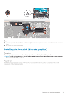
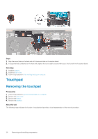
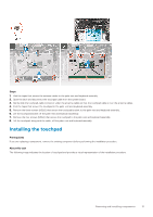
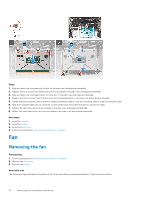
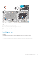
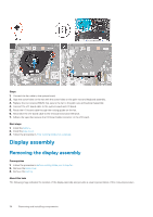
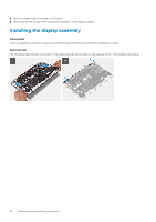
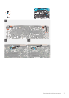
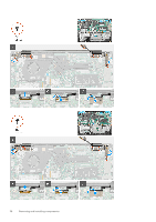
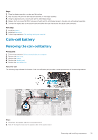
Steps 1. Connect the fan cable to the system board. 2. Align the screw holes on the fan with the screw holes on the palm-rest and keyboard assembly. 3. Replace the two screws (M2x3) that secure the fan to the palm-rest and keyboard assembly. 4. Connect the I/O-board cable to the system board and I/O board. 5. Route the I/O-board cable through the routing guides on the fan. 6. Reconnect the I/O-board cable to the I/O board and close the latch. 7. Adhere the tape that secures the I/O-board cable connector to the I/O board. Next steps 1. Install the battery. 2. Install the base cover. 3. Follow the procedure in After working inside your computer. Display assembly Removing the display assembly Prerequisites 1. Follow the procedure in Before working inside your computer. 2. Remove the base cover. 3. Remove the battery. About this task The following image indicates the location of the display assembly and provides a visual representation of the removal procedure. 34 Removing and installing components
-
 1
1 -
2
-
3
-
4
-
5
-
6
-
7
-
8
-
9
-
10
-
11
-
12
-
13
-
14
-
15
-
16
-
17
-
18
-
19
-
20
-
21
-
22
-
23
-
24
-
25
-
26
-
27
-
28
-
 29
29 -
 30
30 -
 31
31 -
 32
32 -
 33
33 -
 34
34 -
 35
35 -
 36
36 -
 37
37 -
 38
38 -
 39
39 -
40
-
41
-
42
-
43
-
44
-
45
-
46
-
47
-
48
-
49
-
50
-
51
-
52
-
53
-
54
-
55
-
56
-
57
-
58
-
59
-
60
-
61
-
62
-
63
-
64
-
65
-
66
-
67
-
68
-
69
-
70
-
71
 |
 |
