Dell Inspiron 6400 Owner's Manual - Page 126
Lift the display up and away from the computer., Also
 |
View all Dell Inspiron 6400 manuals
Add to My Manuals
Save this manual to your list of manuals |
Page 126 highlights
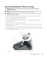
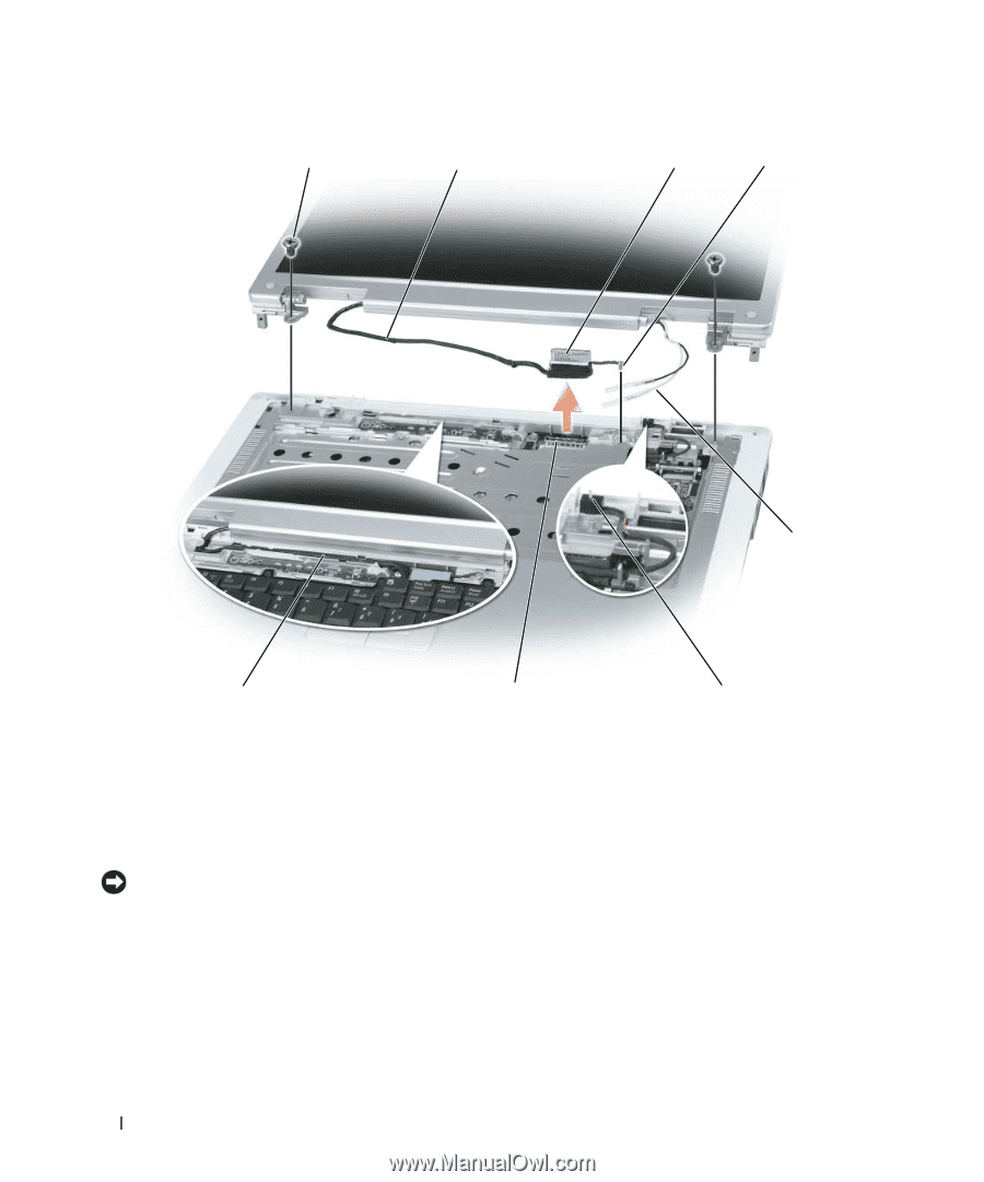
1 2 3 4 5 8 7 6 1 screws (6) 4 grounding-wire screw 7 display cable connector on system board 2 display cable 5 antenna cables 8 display cable channel 3 display cable pull-tab 6 standby switch 8 Lift the display up and away from the computer. NOTICE: The standby switch is fragile and easily broken. Avoid knocking the switch when removing and replacing the display. When you replace the display, ensure that the display cable is lying flat in the display cable channel and securely tucked underneath the tabs. Also, ensure that the antenna cables are not twisted and that they are lying flat in the antenna cable clip. 126 Adding and Replacing Parts
-
 1
1 -
2
-
3
-
4
-
5
-
6
-
7
-
8
-
9
-
10
-
11
-
12
-
13
-
14
-
15
-
16
-
17
-
18
-
19
-
20
-
21
-
22
-
23
-
24
-
25
-
26
-
27
-
28
-
29
-
30
-
31
-
32
-
33
-
34
-
35
-
36
-
37
-
38
-
39
-
40
-
41
-
42
-
43
-
44
-
45
-
46
-
47
-
48
-
49
-
50
-
51
-
52
-
53
-
54
-
55
-
56
-
57
-
58
-
59
-
60
-
61
-
62
-
63
-
64
-
65
-
66
-
67
-
68
-
69
-
70
-
71
-
72
-
73
-
74
-
75
-
76
-
77
-
78
-
79
-
80
-
81
-
82
-
83
-
84
-
85
-
86
-
87
-
88
-
89
-
90
-
91
-
92
-
93
-
94
-
95
-
96
-
97
-
98
-
99
-
100
-
101
-
102
-
103
-
104
-
105
-
106
-
107
-
108
-
109
-
110
-
111
-
112
-
113
-
114
-
115
-
116
-
117
-
118
-
119
-
120
-
 121
121 -
 122
122 -
 123
123 -
 124
124 -
 125
125 -
 126
126 -
 127
127 -
 128
128 -
 129
129 -
 130
130 -
 131
131 -
132
-
133
-
134
-
135
-
136
-
137
-
138
-
139
-
140
-
141
-
142
-
143
-
144
-
145
-
146
-
147
-
148
-
149
-
150
-
151
-
152
-
153
-
154
-
155
-
156
-
157
-
158
-
159
-
160
-
161
-
162
-
163
-
164
-
165
-
166
-
167
-
168
-
169
-
170
-
171
-
172
-
173
-
174
-
175
-
176
-
177
-
178
-
179
-
180
-
181
-
182
-
183
-
184
-
185
-
186
 |
 |
126
Adding and Replacing Parts
8
Lift the display up and away from the computer.
NOTICE:
The standby switch is fragile and easily broken. Avoid knocking the switch when removing and replacing
the display.
When you replace the display, ensure that the display cable is lying flat in the display cable channel and
securely tucked underneath the tabs.
Also, ensure that the antenna cables are not twisted and that they are lying flat in the antenna cable clip.
1
screws (6)
2
display cable
3
display cable pull-tab
4
grounding-wire screw
5
antenna cables
6
standby switch
7
display cable connector on
system board
8
display cable channel
7
2
8
3
5
1
4
6