Dell Inspiron 7790 AIO Inspiron 27-7790 Service Manual - Page 47
System-board connectors, About this task
 |
View all Dell Inspiron 7790 AIO manuals
Add to My Manuals
Save this manual to your list of manuals |
Page 47 highlights
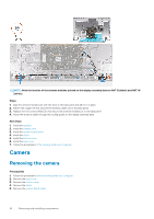
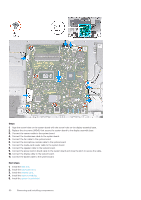
7. Remove the wireless card. 8. Remove the solid-state drive. 9. Remove the heat sink. About this task The following image indicates the connectors on your system board. Figure 1. System-board connectors 1. Memory module 3. Touchscreen cable 5. Coin-cell battery 7. Microphone-module cable 9. Speaker cable 11. Display cable 13. Backlit cable 2. Camera cable 4. Debug port 6. Fan cable 8. Media-card reader cable 10. Power-button board cable 12. Hard-drive connector The following image indicates the location of system board and provides a visual representation of the removal procedure. Removing and installing components 47
-
 1
1 -
2
-
3
-
4
-
5
-
6
-
7
-
8
-
9
-
10
-
11
-
12
-
13
-
14
-
15
-
16
-
17
-
18
-
19
-
20
-
21
-
22
-
23
-
24
-
25
-
26
-
27
-
28
-
29
-
30
-
31
-
32
-
33
-
34
-
35
-
36
-
37
-
38
-
39
-
40
-
41
-
 42
42 -
 43
43 -
 44
44 -
 45
45 -
 46
46 -
 47
47 -
 48
48 -
 49
49 -
 50
50 -
 51
51 -
 52
52 -
53
-
54
-
55
-
56
-
57
-
58
-
59
-
60
-
61
-
62
-
63
-
64
-
65
-
66
-
67
-
68
-
69
-
70
-
71
-
72
 |
 |

7.
Remove the
wireless card
.
8.
Remove the
solid-state drive
.
9.
Remove the
heat sink
.
About this task
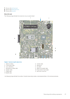
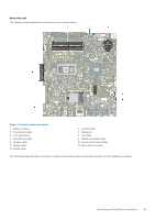
The following image indicates the connectors on your system board.
Figure 1. System-board connectors
1.
Memory module
2.
Camera cable
3.
Touchscreen cable
4.
Debug port
5.
Coin-cell battery
6.
Fan cable
7.
Microphone-module cable
8.
Media-card reader cable
9.
Speaker cable
10.
Power-button board cable
11.
Display cable
12.
Hard-drive connector
13.
Backlit cable
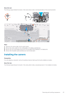
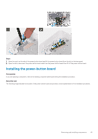
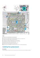
The following image indicates the location of system board and provides a visual representation of the removal procedure.
Removing and installing components
47