Dell Inspiron N5050 Owners Manual - Page 58
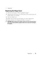
Replacing the Display Assembly
 |
View all Dell Inspiron N5050 manuals
Add to My Manuals
Save this manual to your list of manuals |
Page 58 highlights
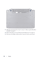
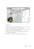
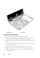
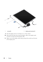
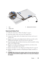
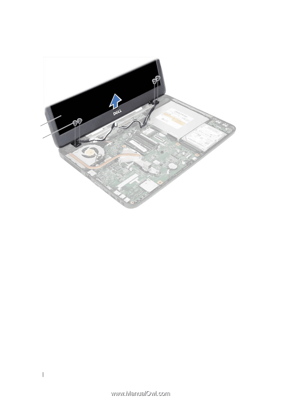
1 2 1 display assembly 2 screws (4) Replacing the Display Assembly 1 Follow the instructions in "Before You Begin" on page 9. 2 Place the display assembly in position and replace the four screws (two on each side) that secure the display assembly to the computer base. 3 Route the display cable and Mini-Card antenna cables through the routing guides. 4 Connect the Mini-Card antenna cables to the Mini-Card. See "Replacing the Mini-Card" on page 27. 5 Connect the display cable to the connector on the system board. 6 Replace the hinge cover. See "Replacing the Hinge Cover" on page 53. 7 Follow the instructions from step 3 to step 7 in "Replacing the Palm-Rest Assembly" on page 32. 58 Display
-
 1
1 -
2
-
3
-
4
-
5
-
6
-
7
-
8
-
9
-
10
-
11
-
12
-
13
-
14
-
15
-
16
-
17
-
18
-
19
-
20
-
21
-
22
-
23
-
24
-
25
-
26
-
27
-
28
-
29
-
30
-
31
-
32
-
33
-
34
-
35
-
36
-
37
-
38
-
39
-
40
-
41
-
42
-
43
-
44
-
45
-
46
-
47
-
48
-
49
-
50
-
51
-
52
-
 53
53 -
 54
54 -
 55
55 -
 56
56 -
 57
57 -
 58
58 -
 59
59 -
 60
60 -
 61
61 -
 62
62 -
 63
63 -
64
-
65
-
66
-
67
-
68
-
69
-
70
-
71
-
72
 |
 |
58
Display
Replacing the Display Assembly
1
Follow the instructions in "Before You Begin" on page 9.
2
Place the display assembly in position and replace the four screws (two on
each side) that secure the display assembly to the computer base.
3
Route the display cable and Mini-Card antenna cables through the routing
guides.
4
Connect the Mini-Card antenna cables to the Mini-Card. See "Replacing
the Mini-Card" on page 27.
5
Connect the display cable to the connector on the system board.
6
Replace the hinge cover. See "Replacing the Hinge Cover" on page 53.
7
Follow the instructions from step 3 to step 7 in "Replacing the Palm-Rest
Assembly" on page 32.
1
display assembly
2
screws (4)
1
2