Dell Latitude 3400 Service Manual - Page 65
Heat sink, Removing the heatsink—UMA
 |
View all Dell Latitude 3400 manuals
Add to My Manuals
Save this manual to your list of manuals |
Page 65 highlights
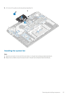
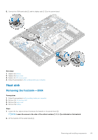
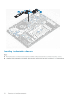
5. Connect the VGA board cable [1], and the display cable [2, 3] to the system board. Next steps 1. Replace the battery. 2. Replace the base cover. 3. Replace the SD memory card. 4. Follow the procedure in after working inside your computer. Heat sink Removing the heatsink-UMA Prerequisites 1. Follow the procedure in before working inside your computer. 2. Remove the SD memory card. 3. Remove the base cover. 4. Remove the battery. Steps 1. Loosen the four captive screws that secure the heatsink to the system board [1]. NOTE: Loosen the screws in the order of the callout numbers [1, 2, 3, 4] as indicated on the heatsink. 2. Lift the heatsink off the system board [2]. Removing and installing components 65
-
 1
1 -
2
-
3
-
4
-
5
-
6
-
7
-
8
-
9
-
10
-
11
-
12
-
13
-
14
-
15
-
16
-
17
-
18
-
19
-
20
-
21
-
22
-
23
-
24
-
25
-
26
-
27
-
28
-
29
-
30
-
31
-
32
-
33
-
34
-
35
-
36
-
37
-
38
-
39
-
40
-
41
-
42
-
43
-
44
-
45
-
46
-
47
-
48
-
49
-
50
-
51
-
52
-
53
-
54
-
55
-
56
-
57
-
58
-
59
-
 60
60 -
 61
61 -
 62
62 -
 63
63 -
 64
64 -
 65
65 -
 66
66 -
 67
67 -
 68
68 -
 69
69 -
 70
70 -
71
-
72
-
73
-
74
-
75
-
76
-
77
-
78
-
79
-
80
-
81
-
82
-
83
-
84
-
85
-
86
-
87
-
88
-
89
-
90
-
91
-
92
-
93
-
94
-
95
-
96
-
97
-
98
-
99
-
100
-
101
-
102
-
103
-
104
-
105
-
106
-
107
-
108
-
109
-
110
-
111
-
112
-
113
-
114
-
115
 |
 |

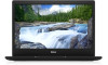
5.
Connect the VGA board cable [1], and the display cable [2, 3] to the system board.
Next steps
1.
Replace the
battery
.
2.
Replace the
base cover
.
3.
Replace the
SD memory card
.
4.
Follow the procedure in
after working inside your computer
.
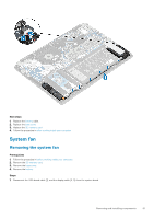
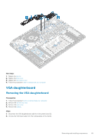
Heat sink
Removing the heatsink—UMA
Prerequisites
1.
Follow the procedure in
before working inside your computer
.
2.
Remove the
SD memory card
.
3.
Remove the
base cover
.
4.
Remove the
battery
.
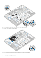
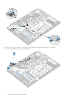
Steps
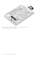
1.
Loosen the four captive screws that secure the heatsink to the system board [1].
NOTE:
Loosen the screws in the order of the callout numbers [1, 2, 3, 4] as indicated on the heatsink.
2.
Lift the heatsink off the system board [2].
Removing and installing components
65