Dell Latitude C800 Service Manual - Page 32
Removing the Display Assembly Bezel
 |
View all Dell Latitude C800 manuals
Add to My Manuals
Save this manual to your list of manuals |
Page 32 highlights
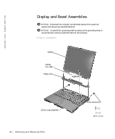
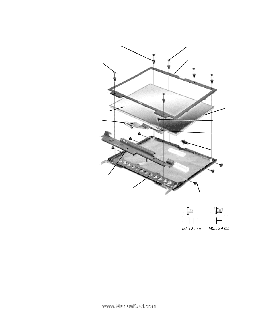
w w w.d el l.co m | su p po rt. d ell. com Display Assembly Bezel and Panel 4-mm screws (6) plastic screw covers (2) rubber screw covers (4) display assembly bezel display panel flex cable hinge cover top cover plastic tabs (6) 4-mm screw flex cable mounting bracket display latch 3-mm screws (6) Removing the Display Assembly Bezel 1 Use a scribe to pry out the four rubber screw covers located across the top of the bezel. 30 Rem o vi n g an d Rep l a ci n g Pa rt s
-
 1
1 -
2
-
3
-
4
-
5
-
6
-
7
-
8
-
9
-
10
-
11
-
12
-
13
-
14
-
15
-
16
-
17
-
18
-
19
-
20
-
21
-
22
-
23
-
24
-
25
-
26
-
 27
27 -
 28
28 -
 29
29 -
 30
30 -
 31
31 -
 32
32 -
 33
33 -
 34
34 -
 35
35 -
 36
36 -
 37
37 -
38
-
39
-
40
-
41
-
42
-
43
-
44
-
45
-
46
-
47
-
48
-
49
-
50
-
51
-
52
-
53
-
54
-
55
-
56
-
57
-
58
-
59
-
60
-
61
-
62
 |
 |
30
Removing and Replacing Parts
www.dell.com | support.dell.com
Display Assembly Bezel and Panel
Removing the Display Assembly Bezel
1
Use a scribe to pry out the four rubber screw covers located across the
top of the bezel.
display panel
top cover
flex cable
4-mm screws (6)
display
latch
rubber screw covers (4)
plastic screw
covers (2)
3-mm screws (6)
display assembly bezel
hinge cover
plastic
tabs (6)
4-mm
screw
flex cable
mounting
bracket