Dell Latitude D500 Service Manual - Page 62
Installing the Microprocessor Module - bios update
 |
View all Dell Latitude D500 manuals
Add to My Manuals
Save this manual to your list of manuals |
Page 62 highlights
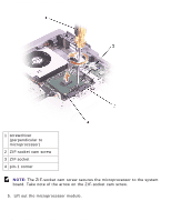
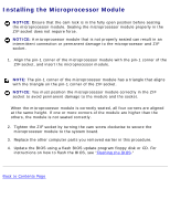
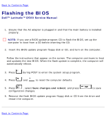
Microprocessor Module: Dell Latitude D500 Service Manual Installing the Microprocessor Module NOTICE: Ensure that the cam lock is in the fully open position before seating the microprocessor module. Seating the microprocessor module properly in the ZIF socket does not require force. NOTICE: A microprocessor module that is not properly seated can result in an intermittent connection or permanent damage to the microprocessor and ZIF socket. 1. Align the pin-1 corner of the microprocessor module with the pin-1 corner of the ZIF socket, and insert the microprocessor module. NOTE: The pin-1 corner of the microprocessor module has a triangle that aligns with the triangle on the pin-1 corner of the ZIF socket. NOTICE: You must position the microprocessor module correctly in the ZIF socket to avoid permanent damage to the module and the socket. When the microprocessor module is correctly seated, all four corners are aligned at the same height. If one or more corners of the module are higher than the others, the module is not seated correctly. 2. Tighten the ZIF socket by turning the cam screw clockwise to secure the microprocessor module to the system board. 3. Replace the other computer parts you removed earlier in this procedure. 4. Update the BIOS using a flash BIOS update program floppy disk or CD. For instructions on how to flash the BIOS, see "Flashing the BIOS." Back to Contents Page file:///F|/Service%20Manuals/Dell/Latitude/d500/cpu.htm (3 of 3) [2/28/2004 8:08:31 AM]
-
 1
1 -
2
-
3
-
4
-
5
-
6
-
7
-
8
-
9
-
10
-
11
-
12
-
13
-
14
-
15
-
16
-
17
-
18
-
19
-
20
-
21
-
22
-
23
-
24
-
25
-
26
-
27
-
28
-
29
-
30
-
31
-
32
-
33
-
34
-
35
-
36
-
37
-
38
-
39
-
40
-
41
-
42
-
43
-
44
-
45
-
46
-
47
-
48
-
49
-
50
-
51
-
52
-
53
-
54
-
55
-
56
-
 57
57 -
 58
58 -
 59
59 -
 60
60 -
 61
61 -
 62
62 -
 63
63 -
 64
64 -
 65
65 -
 66
66 -
 67
67 -
68
-
69
-
70
-
71
-
72
-
73
-
74
-
75
 |
 |