Dell OptiPlex 270 Service Manual - Page 20
Jumper Settings, Resetting CMOS Settings - cpu fan
 |
View all Dell OptiPlex 270 manuals
Add to My Manuals
Save this manual to your list of manuals |
Page 20 highlights
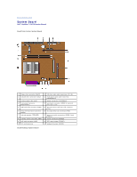
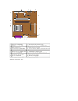
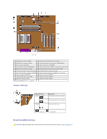
1 floppy-drive connector (DSKT) 12 CD drive audio cable connector (CD_IN) 2 CD/DVD drive connector (IDE2) 13 front-panel audio cable connector (FRONTAUDIO) 3 battery socket (BATTERY) 14 power connector (12VPOWER) 4 front-panel connector (FRONTPANEL) 15 serial port connector (SER2) for optional serial port cards 5 IDE hard-drive connector (IDE1) 16 microprocessor and heat sink connector (CPU) 6 serial ATA hard-drive connector (SATA2) 17 microprocessor fan connector (FAN) 7 serial ATA hard-drive connector (SATA1) 18 memory module connectors (DIMMs 1, 3, 2, and 4) 8 internal speaker (SPEAKER) 19 power connector (POWER) 9 standby power light (AUX_PWR) 20 RTC reset jumper (RTCRST) 10 AGP card connector (AGP) 21 password jumper (PSWD) 11 PCI connectors (PCI 1, 2, 3, and 4)) Jumper Settings Jumper Setting PSWD (default) RTCRST Description Password features are enabled. Password features are disabled. Real-time clock reset. jumpered unjumpered Resetting CMOS Settings CAUTION: Before you begin any of the procedures in this section, follow the steps in "Safety Instructions."
-
 1
1 -
2
-
3
-
4
-
5
-
6
-
7
-
8
-
9
-
10
-
11
-
12
-
13
-
14
-
 15
15 -
 16
16 -
 17
17 -
 18
18 -
 19
19 -
 20
20 -
 21
21 -
 22
22 -
 23
23 -
 24
24 -
 25
25
 |
 |
