Dell OptiPlex 3020 Dell OptiPlex 3020-Mini Tower Owners Manual - Page 55
supported2 SATA Gen3 for HDD. 1 SATA Gen2 for, VGA *1/DP*1/RJ45*1/USB3.0*2/USB2.0*4/Line inMIC *1 - video outputs
 |
View all Dell OptiPlex 3020 manuals
Add to My Manuals
Save this manual to your list of manuals |
Page 55 highlights
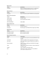
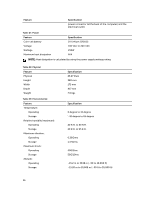
Feature Video Table 25. Internal Connectors Feature System power System fans Processor fans HDD fans Memory Processor Back I/O: Front I/O: Hard drive/ Optical drive: SATA Power Table 26. Controls and Lights Feature Front of the computer: Power button light Drive activity light Back of the computer: Link integrity light on integrated network adapter Network activity light on integrated network adapter Power supply diagnostic light Specification VGA and DP output support on rear I/O side Specification single power rail 290 W PSU(4 pin cable for CPU power/ 8 Pin cable for system power) 1 system FAN connector on rear side 1 CPU FAN connector near CPU N/A 2 DDR slot supported Intel LGA1150 CPU socket VGA *1/DP*1/RJ45*1/USB3.0*2/USB2.0*4/Line in(MIC) *1/ Line out *1 USB2.0 *2 and MIC*1 /HP *1 supported on front panel 3 SATA supported(2 SATA Gen3 for HDD. 1 SATA Gen2 for ODD) single power rail 290W PSU Specification White light - Solid white light indicates power-on state; Breathing white light indicates sleep state of the computer. White light - Blinking white light indicates that the computer is reading data from or writing data to the hard drive Green - a good 10 Mbps connection exists between the network and the computer. Green - a good 100 Mbps connection exists between the network and the computer. Orange - a good 1000 Mbps connection exists between the network and the computer. Off (no light) - the computer is not detecting a physical connection to the network. Yellow light - A blinking yellow light indicates that network activity is present. Green light - The power supply is turned on and is functional. The power cable must be connected to the 55
-
 1
1 -
2
-
3
-
4
-
5
-
6
-
7
-
8
-
9
-
10
-
11
-
12
-
13
-
14
-
15
-
16
-
17
-
18
-
19
-
20
-
21
-
22
-
23
-
24
-
25
-
26
-
27
-
28
-
29
-
30
-
31
-
32
-
33
-
34
-
35
-
36
-
37
-
38
-
39
-
40
-
41
-
42
-
43
-
44
-
45
-
46
-
47
-
48
-
49
-
 50
50 -
 51
51 -
 52
52 -
 53
53 -
 54
54 -
 55
55 -
 56
56 -
 57
57 -
 58
58 -
 59
59
 |
 |