Dell OptiPlex 7090 Tower Setup and Specifications - Page 11
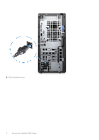
System board Layout
 |
View all Dell OptiPlex 7090 Tower manuals
Add to My Manuals
Save this manual to your list of manuals |
Page 11 highlights
System board Layout 1. CPU power connector 2. Processor fan connector 3. Memory module connector 4. Power button connector 5. Remote power switch connector 6. SD card reader connector 7. SATA0 connector (blue) 8. M.2 PCIe SSD connector 9. Internal USB connector 10. Two SATA1/2 connector (black) 11. SATA3 connector (white) 12. SATA power cable connector 13. Coin-cell battery 14. M.2 WLAN connector 15. System power connector 16. Internal speaker connector 17. Thunderbolt header 18. M.2 PCIe SSD connector 19. PCIe x4 (Slot4) 20. PCI (Slot3) 21. PCIe x16 (Slot2) 22. PCIE x1 (Slot1) 23. System fan connector 24. Chassis Intrusion Detection connector 25. Type-C connector 26. Processor socket 27. Video connector Views of OptiPlex 7090 Tower 11
-
 1
1 -
2
-
3
-
4
-
5
-
 6
6 -
 7
7 -
 8
8 -
 9
9 -
 10
10 -
 11
11 -
 12
12 -
 13
13 -
 14
14 -
 15
15 -
 16
16 -
17
-
18
-
19
-
20
-
21
-
22
-
23
-
24
-
25
 |
 |

System board Layout
1.
CPU power connector
2.
Processor fan connector
3.
Memory module connector
4.
Power button connector
5.
Remote power switch connector
6.
SD card reader connector
7.
SATA0 connector (blue)
8.
M.2 PCIe SSD connector
9.
Internal USB connector
10.
Two SATA1/2 connector (black)
11.
SATA3 connector (white)
12.
SATA power cable connector
13.
Coin-cell battery
14.
M.2 WLAN connector
15.
System power connector
16.
Internal speaker connector
17.
Thunderbolt header
18.
M.2 PCIe SSD connector
19.
PCIe x4 (Slot4)
20.
PCI (Slot3)
21.
PCIe x16 (Slot2)
22.
PCIE x1 (Slot1)
23.
System fan connector
24.
Chassis Intrusion Detection connector
25.
Type-C connector
26.
Processor socket
27.
Video connector
Views of OptiPlex 7090 Tower
11