Dell OptiPlex 745c Quick Reference Guide - Page 11
Mini Tower Computer - Back-Panel Connectors, Tower Computer - Back-Panel Connectors - manual
 |
View all Dell OptiPlex 745c manuals
Add to My Manuals
Save this manual to your list of manuals |
Page 11 highlights
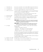
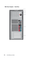
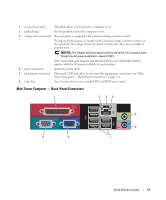
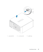
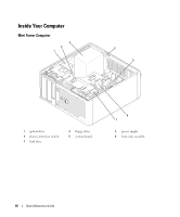
1 cover-release latch This latch allows you to open the computer cover. 2 padlock ring Insert a padlock to lock the computer cover. 3 voltage selection switch Your computer is equipped with a manual voltage-selection switch. To help avoid damaging a computer with a manual voltage-selection switch, set the switch for the voltage that most closely matches the AC power available in your location. NOTICE: The voltage selection switch must be set to the 115-V position even though the AC power available in Japan is 100 V. Also, ensure that your monitor and attached devices are electrically rated to operate with the AC power available in your location. 4 power connector Insert the power cable. 5 back-panel connectors Plug serial, USB, and other devices into the appropriate connectors (see "Mini Tower Computer - Back-Panel Connectors" on page 11). 6 card slots Access connectors for any installed PCI and PCI Express cards. Mini Tower Computer - Back-Panel Connectors 1 2 34 9 8 5 6 7 Quick Reference Guide 11
-
 1
1 -
2
-
3
-
4
-
5
-
 6
6 -
 7
7 -
 8
8 -
 9
9 -
 10
10 -
 11
11 -
 12
12 -
 13
13 -
 14
14 -
 15
15 -
 16
16 -
17
-
18
-
19
-
20
-
21
-
22
-
23
-
24
-
25
-
26
-
27
-
28
-
29
-
30
-
31
-
32
-
33
-
34
-
35
-
36
 |
 |