Dell OptiPlex 790 Technical Guidebook - Page 7
Microphone Connector, Headphone Connector, Power Button, Power, Light, Diagnostic Lights 4, Drive - diagnostic lights 3
 |
View all Dell OptiPlex 790 manuals
Add to My Manuals
Save this manual to your list of manuals |
Page 7 highlights
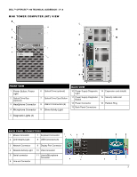
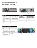
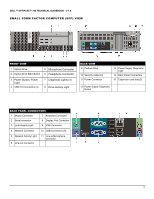
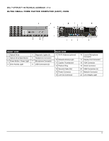
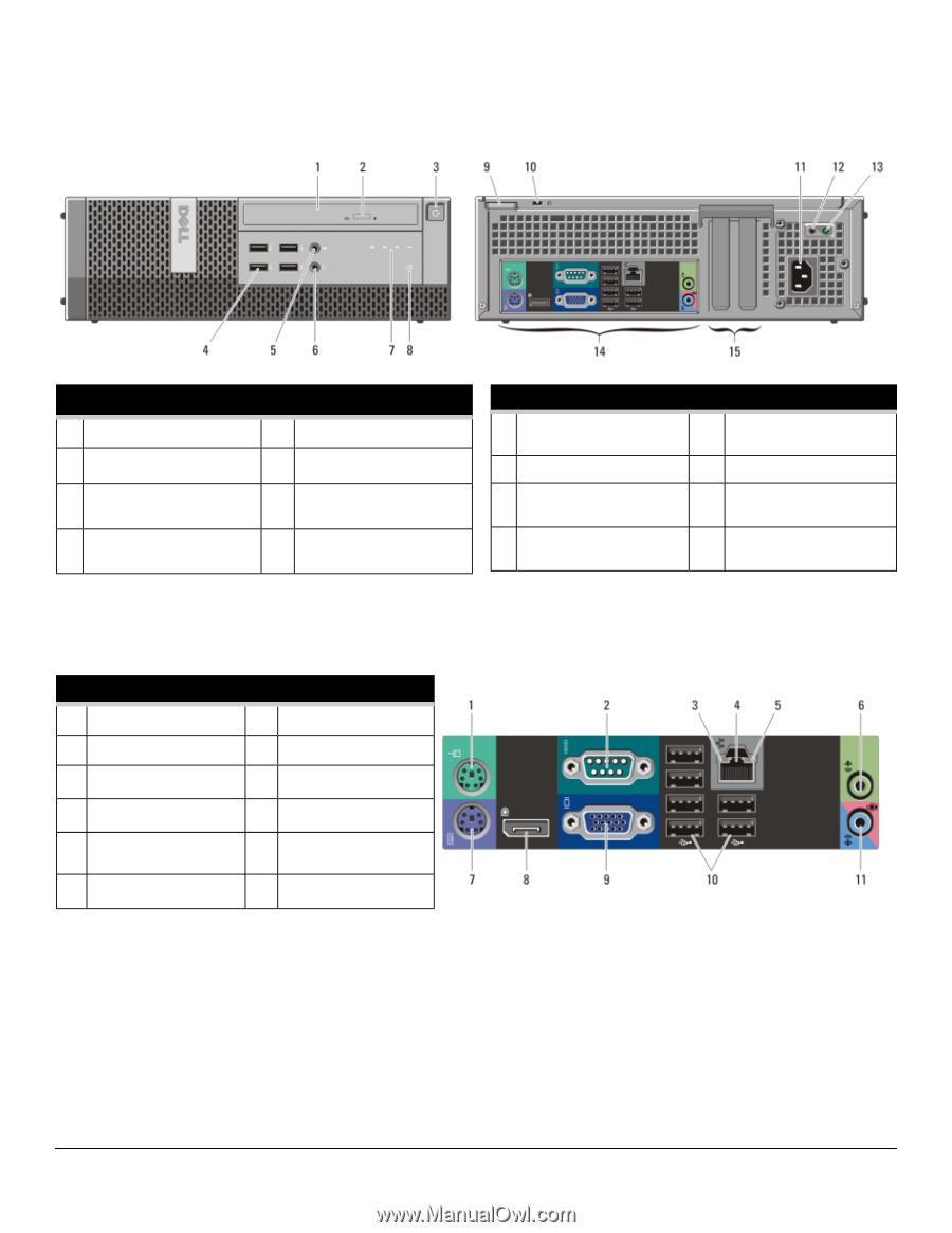
DELL™ OPTIPLEX™ 790 TECHNICAL GUIDEBOOK - V 1.6 SMALL FORM FACTOR COMPUTER (SFF) VIEW FRONT VIEW 1 Optical Drive 2 Optical Drive Eject Button 5 Microphone Connector 6 Headphone Connector 3 Power Button, Power Light 4 USB 2.0 Connectors (4) 7 Diagnostic Lights (4) 8 Drive Activity Light BACK VIEW 9 Padlock Ring 10 Security cable slot 11 Power Connector 13 Power Supply Diagnostic Light 14 Back Panel Connectors 15 Expansion card slots(2) 12 Power Supply Diagnostic Button BACK PANEL CONNECTORS 1 Mouse Connector 7 Keyboard Connector 2 Serial connector 8 Display Port Connector 3 Link Integrity Light 9 VGA Connector 4 Network Connector 10 USB Connectors (6) 5 Network Activity Light 6 Line-out Connector 11 Line-in/Microphone connector 7
-
 1
1 -
 2
2 -
 3
3 -
 4
4 -
 5
5 -
 6
6 -
 7
7 -
 8
8 -
 9
9 -
 10
10 -
 11
11 -
 12
12 -
13
-
14
-
15
-
16
-
17
-
18
-
19
-
20
-
21
-
22
-
23
-
24
-
25
-
26
-
27
-
28
-
29
-
30
-
31
-
32
-
33
-
34
-
35
-
36
-
37
-
38
-
39
-
40
-
41
-
42
-
43
-
44
-
45
-
46
-
47
 |
 |
DELL™ OPTIPLEX™ 790
TECHNICAL GUIDEBOOK - V 1.6
7
FRONT VIEW
1
Optical Drive
5
Microphone Connector
2
Optical Drive Eject Button
6
Headphone Connector
3
Power Button, Power
Light
7
Diagnostic Lights (4)
4
USB 2.0 Connectors (4)
8
Drive Activity Light
BACK VIEW
9 Padlock Ring
13
Power Supply Diagnostic
Light
10 Security cable slot
14
Back Panel Connectors
11 Power Connector
15
Expansion card slots(2)
12 Power Supply Diagnostic
Button
BACK PANEL CONNECTORS
1
Mouse Connector
7
Keyboard Connector
2
Serial connector
8
Display Port Connector
3
Link Integrity Light
9
VGA Connector
4
Network Connector
10 USB Connectors (6)
5
Network Activity Light
11 Line-in/Microphone
connector
6
Line-out Connector
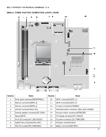
SMALL FORM FACTOR COMPUTER (SFF) VIEW