Dell PowerConnect 3048 System Information Guide - Page 13
Before You Connect to the Network: Mounting Kit Instructions, Dell PowerConnect CD - switch connections
 |
View all Dell PowerConnect 3048 manuals
Add to My Manuals
Save this manual to your list of manuals |
Page 13 highlights
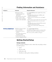
• Rackmount kit for rack installation • Dell PowerConnect CD Before You Connect to the Network: Mounting Kit Instructions NOTICE: Do not connect the switch to the network until you have established the correct Internet Protocol (IP) settings. Before you connect to the network, you must install the switch on a flat surface or in a rack, set up a terminal emulation program, and plug in the power cable. Then you will set up a password and IP address. The switch is supplied with rubber feet for stationing it on a flat surface and mounting brackets and screws for mounting it in a rack. Installing on a Flat Surface The switch can be installed on any appropriate level surface that can safely support the weight of the hubs and their attached cables. There must be adequate space around the switch for ventilation and access to cable connectors. To install the switch on a flat surface: 1 Set the switch on the flat surface and check for proper ventilation. Allow at least 5.1 cm (2 inches) on each side for proper ventilation and 12.7 cm (5 inches) at the back for power cable clearance. 2 Attach rubber feet on each marked location on the bottom of the chassis. The rubber feet are optional but recommended to keep the unit from slipping. Installing in a Rack The switch can be installed in most standard 48.3-cm (19-inch) racks. To install the switch in a rack: 1 Use the supplied screws to attach a mounting bracket to each side of the switch. 2 Position the switch in the rack and align the holes in the mounting bracket with the holes in the rack. NOTE: For racks that are not prethreaded, cage nuts are provided. PowerConnect System Infor mation Guide 11
-
 1
1 -
2
-
3
-
4
-
5
-
6
-
7
-
 8
8 -
 9
9 -
 10
10 -
 11
11 -
 12
12 -
 13
13 -
 14
14 -
 15
15 -
 16
16 -
 17
17 -
 18
18 -
19
-
20
-
21
-
22
-
23
-
24
-
25
-
26
-
27
-
28
-
29
-
30
-
31
-
32
-
33
-
34
-
35
-
36
-
37
-
38
-
39
-
40
-
41
-
42
-
43
-
44
-
45
-
46
-
47
-
48
-
49
-
50
-
51
-
52
-
53
-
54
-
55
-
56
-
57
-
58
-
59
-
60
-
61
-
62
-
63
-
64
-
65
-
66
-
67
-
68
-
69
-
70
-
71
-
72
-
73
-
74
-
75
-
76
-
77
-
78
-
79
-
80
-
81
-
82
-
83
-
84
-
85
-
86
-
87
-
88
-
89
-
90
-
91
-
92
-
93
-
94
-
95
-
96
-
97
-
98
-
99
-
100
-
101
-
102
-
103
-
104
-
105
-
106
-
107
-
108
-
109
-
110
-
111
-
112
-
113
-
114
-
115
-
116
-
117
-
118
-
119
-
120
-
121
-
122
-
123
-
124
-
125
-
126
-
127
-
128
-
129
-
130
-
131
-
132
-
133
-
134
-
135
-
136
-
137
-
138
-
139
-
140
-
141
-
142
-
143
-
144
-
145
-
146
-
147
-
148
-
149
-
150
-
151
-
152
-
153
-
154
-
155
-
156
-
157
-
158
-
159
-
160
-
161
-
162
-
163
-
164
-
165
-
166
-
167
-
168
-
169
-
170
-
171
-
172
-
173
-
174
-
175
-
176
 |
 |
