Dell PowerConnect B-RX4 Installation Guide - Page 118
Installing a fiber optic module, Connecting a BigIron RX Series switch
 |
View all Dell PowerConnect B-RX4 manuals
Add to My Manuals
Save this manual to your list of manuals |
Page 118 highlights
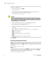
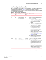
4 Connecting a BigIron RX Series switch TABLE 15 Fiber optic modules and cabling (Continued) Fiber optic modules (PMD) Distance Fiber optic cabling Long wavelength 1310 nm serial Extra long wavelength 1550 nm serial 10 km 40 km 9/125 micron single-mode fiber with LC connectors 9/125 micron single-mode fiber with LC connectors Brocade part number 10G-XFP-LR 10G-XFP-ER NOTE Cable installation and network configuration will affect overall transmission capability. The numbers provided above represent the accepted recommendations of the various standards. For network-specific recommendations, consult your local Brocade reseller or system engineer. To connect a BigIron RX Series switch to another network device, you must do the following: • Install the fiber optic modules • Cable the fiber optic modules The following sections provide information about performing these tasks as well as cleaning the fiber optic connectors and troubleshooting network connections. Installing a fiber optic module You connect a BigIron RX Series switch to another network device using a fiber port, you must do the following: • Install a fiber optic module (SFP transceiver for Gigabit Ethernet ports or SFP-MSA transceiver for 10-Gigabit Ethernet ports) DANGER All fiber optic interfaces use Class 1 Lasers. NOTE Refer to "Installation precautions" on page 25 for other hardware installation precautions. Before installing a fiber optic module, have on hand an ESD wrist strap with a plug for connection to the ESD connector on the BigIron RX Series chassis. DANGER For safety reasons, the ESD wrist strap should contain a 1 meg ohm series resistor. To install a fiber optic module into an Ethernet port, do the following. 1. Put on the ESD wrist strap and ground yourself by inserting the plug into the ESD connector located in the upper right corner of the chassis front. 2. Remove the module from its protective packaging. 3. Remove the metal cover from the port on the interface module's control panel. 106 BigIron RX Installation Guide 53-1001811-01
-
 1
1 -
2
-
3
-
4
-
5
-
6
-
7
-
8
-
9
-
10
-
11
-
12
-
13
-
14
-
15
-
16
-
17
-
18
-
19
-
20
-
21
-
22
-
23
-
24
-
25
-
26
-
27
-
28
-
29
-
30
-
31
-
32
-
33
-
34
-
35
-
36
-
37
-
38
-
39
-
40
-
41
-
42
-
43
-
44
-
45
-
46
-
47
-
48
-
49
-
50
-
51
-
52
-
53
-
54
-
55
-
56
-
57
-
58
-
59
-
60
-
61
-
62
-
63
-
64
-
65
-
66
-
67
-
68
-
69
-
70
-
71
-
72
-
73
-
74
-
75
-
76
-
77
-
78
-
79
-
80
-
81
-
82
-
83
-
84
-
85
-
86
-
87
-
88
-
89
-
90
-
91
-
92
-
93
-
94
-
95
-
96
-
97
-
98
-
99
-
100
-
101
-
102
-
103
-
104
-
105
-
106
-
107
-
108
-
109
-
110
-
111
-
112
-
 113
113 -
 114
114 -
 115
115 -
 116
116 -
 117
117 -
 118
118 -
 119
119 -
 120
120 -
 121
121 -
 122
122 -
 123
123 -
124
-
125
-
126
-
127
-
128
-
129
-
130
-
131
-
132
-
133
-
134
-
135
-
136
-
137
-
138
-
139
-
140
-
141
-
142
-
143
-
144
-
145
-
146
-
147
-
148
-
149
-
150
-
151
-
152
-
153
-
154
-
155
-
156
-
157
-
158
-
159
-
160
-
161
-
162
-
163
-
164
-
165
-
166
-
167
-
168
-
169
-
170
-
171
-
172
-
173
-
174
-
175
-
176
-
177
-
178
-
179
-
180
-
181
-
182
-
183
-
184
-
185
-
186
-
187
-
188
-
189
-
190
-
191
-
192
-
193
-
194
-
195
-
196
-
197
-
198
-
199
-
200
-
201
-
202
-
203
-
204
-
205
-
206
-
207
-
208
-
209
-
210
-
211
-
212
-
213
-
214
-
215
-
216
-
217
-
218
-
219
-
220
-
221
-
222
-
223
-
224
-
225
-
226
-
227
-
228
-
229
-
230
-
231
-
232
-
233
-
234
-
235
-
236
-
237
-
238
-
239
-
240
 |
 |