Dell PowerConnect W-IAP92 Dell PowerConnect W-IAP90 Series Access Point Instal - Page 2
Dell PowerConnect W-IAP90 Series, Instant Access Point
 |
View all Dell PowerConnect W-IAP92 manuals
Add to My Manuals
Save this manual to your list of manuals |
Page 2 highlights
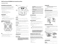
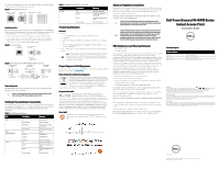
The 10/100/1000 Mbps Ethernet port is on the back of the IAP. The port has an RJ-45 female connector with the pin-outs shown in Figure 5. Figure 5 Gigabit Ethernet Port Pin-Out 1000Base-T Gigabit Ethernet Port RJ-45 Female Pin-Out 1 2 3 4 5 6 7 8 Signal Name BI_DA+ BI_DABI_DB+ BI_DC+ BI_DCBI_DBBI_DD+ BI_DD- Function Bi-directional pair +A Bi-directional pair -A Bi-directional pair +B Bi-directional pair +C Bi-directional pair -C Bi-directional pair -B Bi-directional pair +D Bi-directional pair -D Serial Console Port The serial console port (Console) allows you to connect the IAP to a serial terminal or a laptop for direct local management. This port is an RJ-45 female connector with the pinouts described in Figure 6. Connect this port in one of the following ways: Connect it directly to a terminal or terminal server using an Ethernet cable. Use a modular adapter to convert the RJ-45 (female) connector on the IAP to a DB-9 (male) connector, and connect the adapter to a laptop using an RS-232 cable. See Figure 7 for connector details of the adapter. Figure 6 Serial Port Pin-Out Serial Console Port RJ-45 Female Pin-Out 1 2 3 4 5 6 7 8 Direction Input Output TxD GND GND RxD Figure 7 RJ-45 (Female) to DB-9 (Male) Modular Adapter Conversion RJ-45 Female Pin-Out 1 2 3 TxD 4 5 GND 6 RxD 7 8 Direction Input Output Internal Connections RJ-45 3 TxD 4 5 GND 6 RxD DB-9 2 5 3 DB-9 Male Pin-Out 9 8 7 6 5 4 3 2 1 Direction Input Output Ground RxD TxD Power Connection The W-IAP90 Series has a single 12V DC power jack socket to support powering through an AC-to-DC power adapter. Caution: If both POE and DC power are available, the IAP uses POE even when there is not enough POE voltage available to power the IAP.. Verifying Post-Installation Connectivity The integrated LEDs on the IAP can be used to verify that the IAP is receiving power and initializing successfully (see Table 1). Refer to the Dell PowerConnect W-Instant Quick Start Guide for further details on verifying post-installation network connectivity. Table 1 W-IAP90 Series LED Behavior LED Color/State Meaning PWR ENET (10/100/1000 Mbps) 11A/N Off Green flashing Red steady Green steady Off Green on Amber on Flashing Off Amber Green Green flashing No power to IAP System initializing System failed to initialize, contact TAC Power on, device ready No link 1000 Mbps link 10/100 Mbps link Ethernet link activity 5 GHz radio is disabled 5 GHz radio enabled in 11a mode 5 GHz radio enabled in 11n mode 5 GHz Air Monitor Table 1 W-IAP90 Series LED Behavior (Continued) LED Color/State 11B/G/N Off Amber Green Green flashing Meaning 2.4 GHz radio disabled 2.4 GHz radio enabled in 11b/g mode 2.4 GHz radio enabled in 11n mode 2.4 GHz Air Monitor Product Specifications Electrical Ethernet: 1 x 10/100/1000Base-T auto-sensing Ethernet RJ-45 Interfaces MDI/MDX IEEE 802.3 (10Base-T), IEEE 802.3u (100Base-T). IEEE 802.3ab (1000BaseT) Power over Ethernet (IEEE 802.3af compliant), 48V DC/350mA (see Figure 5 for pin configuration) Power: 12 VDC power interface, supports powering through an AC-to-DC power adapter Note: If a power adapter other than the one provided by Dell is used in the US or Canada, it should be cULus (NRTL) Listed, with an output rated 12 VDC, minimum 1.25A, marked "LPS" or "Class 2," and suitable for plugging into a standard power receptacle in the US and Canada. Proper Disposal of Dell Equipment For the most current information about Global Environmental Compliance and Dell products, see our website at www.dell.com. Waste of Electrical and Electronic Equipment Dell products at end of life are subject to separate collection and treatment in the EU Member States, Norway, and Switzerland and therefore are marked with the symbol shown at the left (crossedout wheelie bin). The treatment applied at end of life of these products in these countries shall comply with the applicable national laws of countries implementing Directive 2002/96EC on Waste of Electrical and Electronic Equipment (WEEE). European Union RoHS Dell products also comply with the EU Restriction of Hazardous Substances Directive 2002/95/EC (RoHS). EU RoHS restricts the use of specific hazardous materials in the manufacture of electrical and electronic equipment. Specifically, restricted materials under the RoHS Directive are Lead (including Solder used in printed circuit assemblies), Cadmium, Mercury, Hexavalent Chromium, and Bromine. Some Dell products are subject to the exemptions listed in RoHS Directive Annex 7 (Lead in solder used in printed circuit assemblies). Products and packaging will be marked with the "RoHS" label shown at the left indicating conformance to this Directive. China RoHS Dell products also comply with China environmental declaration 10 requirements and are labeled with the "EFUP 10" label shown at the left. Safety and Regulatory Compliance Dell provides a multi-language document containing country specific restrictions and additional safety and regulatory information for all Dell hardware products. The Dell PowerConnect W-Series Safety, Environmental, and Regulatory Information document is included with this product. The device will be electronically labeled and the FCC ID will be displayed via the controller WebUI under the About menu. Caution: Dell access points must be installed by a professional installer. The professional installer is responsible for ensuring that grounding is available and it meets applicable local and national electrical codes. Caution: RF Radiation Exposure Statement: This equipment complies with FCC RF radiation exposure limits. This equipment should be installed and operated with a minimum distance of 7.87 inches (20cm) between the radiator and your body for 2.4 GHz and 5 GHz operations. This transmitter must not be co-located or operating in conjunction with any other antenna or transmitter. When operated in the 5.15 to 5.25 GHz frequency range, this device is restricted to indoor use. Dell PowerConnect W-IAP90 Series Instant Access Point Installation Guide EMC Compliance and Warning Statement IEC 60601-1-2: 2007 EN 60601-1-2: 2007 This equipment has been tested and found to comply with the limits of the standard for medical devices, IEC 60601-1-2:2007. The unit also complies with the requirements of EN 60601-1-2:2007, providing the presumption of compliance to the European Union's Medical Device Directive 2007/47/EC. The limits are designed to provide reasonable protection against harmful interference in a typical medical installation. This equipment generates, uses and can radiate radio frequency energy, and, if not installed and used in accordance with the manufacturer's instructions may cause harmful interference to other devices in the vicinity. However, there is no guarantee that interference will not occur in a particular installation. If this equipment causes interference with other devices, which may be determined by turning the equipment off and on, the user is encouraged to try and correct the interference by one or more of the following measures: Reorient or relocate the device receiving the interference. Increase the separation between the equipment. Connect the equipment into an outlet on a circuit different from that to which the other device(s) are connected. Consult the manufacturer or field service technician for help. The Models W-IAP92 and W-IAP93 do not have an Applied Part as defined in IEC 60601-1. The protection against electric shock is Class ll. Device is not protected against ingress of liquids and has a protection class of IPX0 as defined by IEC 60601-1 and IEC 60529. Equipment not suitable for use in the presence of flammable mixtures. The unit is considered "Continuous Operation" equipment as defined by IEC 606011. Power Consumption - 48 VDC 802.3af power over Ethernet or 12VDC, 1.25A for external AC supplied power (adapter sold separately); Maximum power consumption - 10W. Mechanical Dimensions: 120mm x 130mm x 55mm; 255g. Environmental: Operating Temp: 0° C to +50° C (+32° F to +122° F); Humidity: 5 to 95% non-condensing. Storage Temp: -40° CS to +70° C (-40°F to +158°F). Contacting Supports Web Site Support Main Site Support Site Dell Documentation http://www.dell.com https://support.dell.com https://support.dell.com/manuals Copyright © 2011 Aruba Networks, Inc. Aruba Networks trademarks include , Aruba Networks®, Aruba Wireless Networks®, the registered Aruba the Mobile Edge Company logo, and Aruba Mobility Management System®. Dell™, the DELL™ logo, and PowerConnect™ are trademarks of Dell Inc. All rights reserved. Specifications in this manual are subject to change without notice. Originated in the USA. All other trademarks are the property of their respective owners. Open Source Code Certain Aruba products include Open Source software code developed by third parties, including software code subject to the GNU General Public License (GPL), GNU Lesser General Public License (LGPL), or other Open Source Licenses. The Open Source code used can be found at this site: http://www.arubanetworks.com/open_source Legal Notice The use of Aruba Networks, Inc. switching platforms and software, by all individuals or corporations, to terminate other vendors' VPN client devices constitutes complete acceptance of liability by that individual or corporation for this action and indemnifies, in full, Aruba Networks, Inc. from any and all legal actions that might be taken against it with respect to infringement of copyright on behalf of those vendors. www.dell.com Dell PowerConnect W-IAP90 Series Instant Access Point | Installation Guide Part Number 0510942-01 | June 2011
-
 1
1 -
 2
2
 |
 |
