Dell PowerConnect W-Series FIPS Dell PowerConnect W-AP134/5 Security Policy - Page 12
AP-134 TEL Placement
 |
View all Dell PowerConnect W-Series FIPS manuals
Add to My Manuals
Save this manual to your list of manuals |
Page 12 highlights
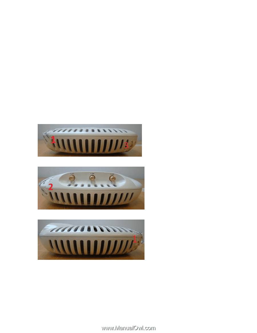
3.2.2 AP-134 TEL Placement This section displays all the TEL locations of the Aruba AP-134. The AP-134 requires a minimum of 5 TELs to be applied as follows: 3.2.2.1 To detect opening of the chassis cover: 1. Spanning the bottom and top chassis covers and placed in the front left corner 2. Spanning the bottom and top chassis covers and placed in the back left corner 3. Spanning the chassis screw on the bottom left corner 4. Spanning the chassis screw on the bottom right corner 3.2.2.2 To detect access to restricted ports 5. Spanning the serial port Following is the TEL placement for the AP-134: Figure 1: AP-134 Front view Figure 2: AP-134 Back View Figure 3: AP-134 Left View 12
-
 1
1 -
2
-
3
-
4
-
5
-
6
-
 7
7 -
 8
8 -
 9
9 -
 10
10 -
 11
11 -
 12
12 -
 13
13 -
 14
14 -
 15
15 -
 16
16 -
 17
17 -
18
-
19
-
20
-
21
-
22
-
23
-
24
-
25
-
26
-
27
-
28
-
29
-
30
-
31
-
32
-
33
-
34
-
35
 |
 |
12
3.2.2 AP-134 TEL Placement
This section displays all the TEL locations of the Aruba AP-134.
The AP-134 requires a minimum of 5
TELs to be applied as follows:
3.2.2.1
To detect opening of the chassis cover:
1.
Spanning the bottom and top chassis covers and placed in the front left corner
2.
Spanning the bottom and top chassis covers and placed in the back left corner
3.
Spanning the chassis screw on the bottom left corner
4.
Spanning the chassis screw on the bottom right corner
3.2.2.2
To detect access to restricted ports
5.
Spanning the serial port
Following is the TEL placement for the AP-134:
Figure 1: AP-134 Front view
Figure 2: AP-134 Back View
Figure 3: AP-134 Left View