Dell PowerEdge 1855 McDATA 4416 Fibre Channel Switch Module - Page 4
Port Side - processors
 |
View all Dell PowerEdge 1855 manuals
Add to My Manuals
Save this manual to your list of manuals |
Page 4 highlights
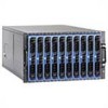
• The following system light-emitting diodes (LEDs): - One green power LED to indicate system power-on - One green/amber LED to indicate system status - One green LED to indicate DRAC/MC status Each SilkWorm 4016 switch contains: • One PowerPC 405GP processor with a clock speed of 200 MHz • One real-time clock with 10-year battery • Five digital thermometers Port Side Externally accessible ports (ports 10 through 15) and all LEDs are on the port side of the switch. The port side faces out when the switch is inserted into a PowerEdge 1855, as shown. A complete description of the locations and interpretations of these LEDs can be found in the SilkWorm 4016 Hardware Reference Manual. The insertion and removal arm is located just above the port side of the SilkWorm 4016. The plastic insertion arm latch, accessible at the front of the port side of the switch, is used to remove and insert the unit. 3 4 2 10 11 12 13 14 15 ! 1 5 Figure 1 SilkWorm 4016 Port Side 1 Ethernet port 2 Power and status LEDs 3 Top of switch 4 Insertion arm latch 5 Autosensing ports 4 of 12 SilkWorm 4016 Quickstart Guide Publication Number: Publication Number: 53-100051-01
-
 1
1 -
 2
2 -
 3
3 -
 4
4 -
 5
5 -
 6
6 -
 7
7 -
 8
8 -
 9
9 -
 10
10 -
11
-
12
 |
 |
