Dell PowerEdge 2550 Installing a Fifth SCSI Hard-Disk Drive - Page 4
Hard-Disk Drive Configuration, Installing a Fifth SCSI Hard-Disk Drive - disk remove
 |
View all Dell PowerEdge 2550 manuals
Add to My Manuals
Save this manual to your list of manuals |
Page 4 highlights
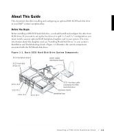
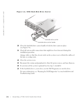
www.dell.com | support.dell.com Hard-Disk Drive Configuration The four hard-disk drives connected to the main SCSI backplane board are designated as SCSI ID 0 through SCSI ID 3 (see Figure 1-1). The fifth hard-disk drive is identified as SCSI ID 4. To operate the five drives in a 1 x 5 configuration, attach a single SCSI host adapter to connector SCSIA on the SCSI backplane board. You can also configure the five drives in a split (1 x 2 and 1 x 3) configuration if you install a second, optional SCSI backplane daughter card and a second SCSI host adapter. In this mode, the host adapter attached to connector SCSIB on the backplane controls slots SCSI ID 0 and SCSI ID 1, while the host adapter connected to connector SCSIA controls slots SCSI ID 2, SCSI ID 3, and the fifth drive slot, SCSI ID 4. Installing a Fifth SCSI Hard-Disk Drive Dell supplies SCSI hard-disk drives in special drive carriers that fit in the hard-disk drive bays. For a drive carrier to fit in the peripheral bay, you must remove the peripheral bay and install a special hard-disk drive cage in the bay. You then reinstall this bay-and-cage assembly and insert the drive carrier into the hard-disk drive cage. WARNING: Before you perform the procedures in this section, you must turn off the system and disconnect it from its AC power source. WARNING: See your System Information document for important safety information before working inside your system. 1 Turn off the system, including any attached peripherals, and disconnect the system from the electrical outlet. 2 Open the system covers. 3 If a bezel is installed, remove it. For more information, see "Removing the Front Bezel" in your system's Installation and Troubleshooting Guide. 4 If a SCSI tape drive or other drive is currently installed in the peripheral bay, disconnect the interface and power cables from the drive. 5 Disconnect all cables connected to the interposer board on top of the peripheral bay (see Figure 1-1). These cables include the system board interface cable, cooling fan wiring harness, interposer board power cable, and control panel cable (see Figure 1-2). 1-2 Installing a Fifth SCSI Hard-Disk Drive
-
 1
1 -
 2
2 -
 3
3 -
 4
4 -
 5
5 -
 6
6 -
 7
7 -
 8
8 -
 9
9 -
 10
10 -
11
-
12
-
13
-
14
-
15
-
16
-
17
-
18
-
19
-
20
-
21
-
22
-
23
-
24
-
25
-
26
-
27
-
28
-
29
-
30
-
31
-
32
 |
 |