Dell PowerEdge 2550 SCSI Backplane Daughter Card - Page 6
SCSI ID 2, and the fifth drive slot, SCSI ID 4 see - daughter card
 |
View all Dell PowerEdge 2550 manuals
Add to My Manuals
Save this manual to your list of manuals |
Page 6 highlights
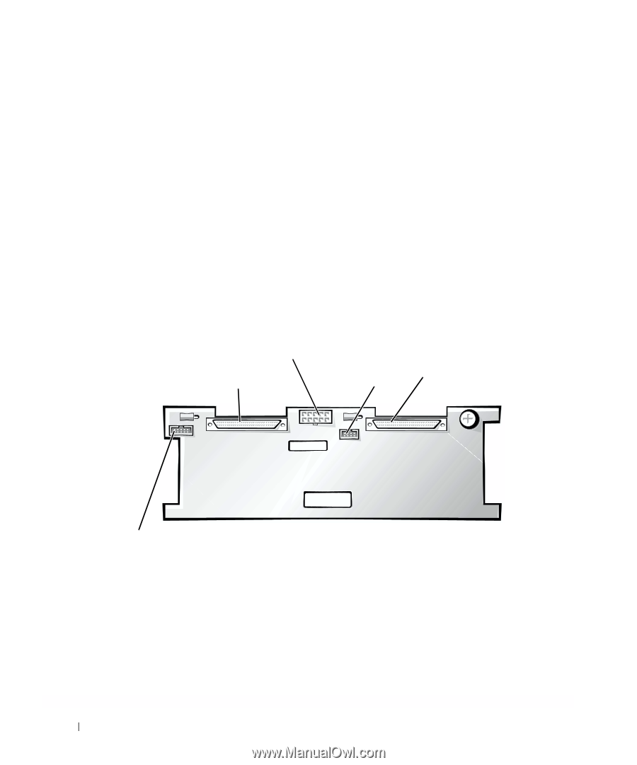
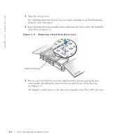
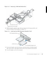
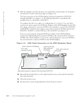
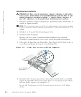
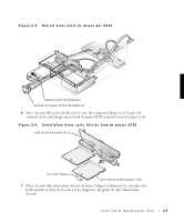
www.dell.com | support.dell.com 9 Slide the daughter card into the drive bay and lock the card into place by closing the retention lever on the card's front edge (see Figure 1-4). The four connectors on the SCSI backplane board are designated as SCSI ID 0 through SCSI ID 3 (see Figure 1-1). If a fifth hard-disk drive is installed in the peripheral bay, it is identified as SCSI ID 4. To configure the drives in a split 2 x 2 configuration (1 x 2 and 1 x 3 in a five-drive system), you must connect two SCSI host adapters to the SCSI backplane board. The host adapter attached to connector SCSIB on the backplane controls slots SCSI ID 0 and SCSI ID 1, while the host adapter connected to connector SCSIA controls slots SCSI ID 2, SCSI ID 3, and the fifth drive slot, SCSI ID 4 (see Figure 1-5). If you are connecting the integrated SCSI host adapter to the SCSI backplane, connect the cable leading from connector SCSIA on the system board to connector SCSIB on the SCSI backplane. Connect the cable leading from connector SCSIB on the system board to connector SCSIA on the SCSI backplane. Figure 1-5. SCSI Cable Connectors on the SCSI Backplane Board power connector (POWER2) SCSI cable connector (SCSIA) system-board data cable connector (PLANAR) SCSI cable connector (SCSIB) data cable connector to optional fifth drive board (DRIVE5) 10 Reinstall the hard-disk drives in the right-hand drive bays and install the hard-disk drive lock if desired. 11 Close the system covers. 12 Reconnect the system and peripherals to their AC power sources. 1-4 SCSI Backplane Daughter Card
-
 1
1 -
 2
2 -
 3
3 -
 4
4 -
 5
5 -
 6
6 -
 7
7 -
 8
8 -
 9
9 -
 10
10 -
 11
11 -
 12
12 -
13
-
14
-
15
-
16
-
17
-
18
-
19
-
20
-
21
-
22
-
23
-
24
-
25
-
26
-
27
-
28
 |
 |