Dell PowerEdge 2650 Rack Installation Guide - Page 31
Perform steps 7 and 8 to install the right slide assembly in the rack.
 |
View all Dell PowerEdge 2650 manuals
Add to My Manuals
Save this manual to your list of manuals |
Page 31 highlights
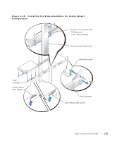
Figure 1-16. Rotating the Front Mounting Bracket for Flush-Mount Installation shoulder washer (2 per bracket) nut (2 per bracket) 12-24 x 0.5-inch pan-head Phillips screws (install 2 per bracket) mounting flange 12-24 x 0.5-inch pan-head Phillips screws (remove 2 per bracket) NOTE: These screws are shown reinstalled on the other slide assembly. 6 Repeat steps 4 and 5 to configure the other slide assembly. 7 Holding the left slide assembly into position in the two-post rack at the location you marked, adjust the extended back bracket tightly against the vertical two-post rack and secure it with three 12-24 x 0.5-inch pan-head Phillips screws (see Figure 1-17). 8 Secure the front bracket on the slide assembly to the two-post rail with two 12-24 x 0.5- inch pan-head Phillips screws (see Figure 1-17). 9 Perform steps 7 and 8 to install the right slide assembly in the rack. 10 Use an 11/32-inch wrench or nut driver to fully tighten the nuts on the mounting brackets on both slide assemblies that you tightened with your fingers. 11 Install the stiffening bracket between the back ends of the slide assemblies and secure the bracket with a 12-24 0.5-inch pan-head Phillips screw on each slide assembly (see Figure 1-17). Rack Installation Guide 1-25
-
 1
1 -
2
-
3
-
4
-
5
-
6
-
7
-
8
-
9
-
10
-
11
-
12
-
13
-
14
-
15
-
16
-
17
-
18
-
19
-
20
-
21
-
22
-
23
-
24
-
25
-
 26
26 -
 27
27 -
 28
28 -
 29
29 -
 30
30 -
 31
31 -
 32
32 -
 33
33 -
 34
34 -
 35
35 -
 36
36 -
37
-
38
-
39
-
40
-
41
-
42
-
43
-
44
-
45
-
46
-
47
-
48
-
49
-
50
-
51
-
52
-
53
-
54
-
55
-
56
-
57
-
58
-
59
-
60
-
61
-
62
-
63
-
64
-
65
-
66
-
67
-
68
-
69
-
70
-
71
-
72
-
73
-
74
-
75
-
76
-
77
-
78
-
79
-
80
-
81
-
82
-
83
-
84
-
85
-
86
-
87
-
88
-
89
-
90
-
91
-
92
-
93
-
94
-
95
-
96
-
97
-
98
-
99
-
100
-
101
-
102
-
103
-
104
-
105
-
106
-
107
-
108
-
109
-
110
-
111
-
112
-
113
-
114
-
115
-
116
-
117
-
118
-
119
-
120
-
121
-
122
-
123
-
124
-
125
-
126
-
127
-
128
-
129
-
130
-
131
-
132
-
133
-
134
-
135
-
136
-
137
-
138
-
139
-
140
-
141
-
142
-
143
-
144
-
145
-
146
-
147
-
148
-
149
-
150
-
151
-
152
-
153
-
154
-
155
-
156
-
157
-
158
-
159
-
160
-
161
-
162
-
163
-
164
-
165
-
166
-
167
-
168
-
169
-
170
-
171
-
172
-
173
-
174
-
175
-
176
-
177
-
178
-
179
-
180
-
181
-
182
-
183
-
184
 |
 |
