Dell PowerEdge 2900 Information Update - Page 24
Updates, System Board Replacement Update, Service-Only Procedure - service manual
 |
View all Dell PowerEdge 2900 manuals
Add to My Manuals
Save this manual to your list of manuals |
Page 24 highlights
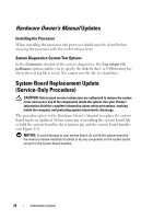
Hardware Owner's Manual Updates Installing the Processor When installing the processor, the processor shield must be closed before securing the processor with the socket release lever. System Diagnostics Custom Test Options In the Customize window of the system diagnostics, the Log output file pathname option enables you to specify the diskette drive or USB memory key where the test log file is saved. You cannot save the file to a hard drive. System Board Replacement Update (Service-Only Procedure) CAUTION: Only trained service technicians are authorized to remove the system cover and access any of the components inside the system. See your Product Information Guide for complete information about safety precautions, working inside the computer, and protecting against electrostatic discharge. The procedure given in the Hardware Owner's Manual to replace the system board has been updated. When removing or installing the system board, lift or hold the system board by the retention pin and the system board handles (see Figure 1-3). NOTICE: To avoid damage to your system board, do not lift the system board by the memory module retention brackets or by any component on the system board except for the system board handles. 24 Information Update
-
 1
1 -
2
-
3
-
4
-
5
-
6
-
7
-
8
-
9
-
10
-
11
-
12
-
13
-
14
-
15
-
16
-
17
-
18
-
 19
19 -
 20
20 -
 21
21 -
 22
22 -
 23
23 -
 24
24 -
 25
25 -
 26
26 -
 27
27 -
 28
28 -
 29
29 -
30
-
31
-
32
-
33
-
34
-
35
-
36
-
37
-
38
-
39
-
40
-
41
-
42
-
43
-
44
-
45
-
46
-
47
-
48
-
49
-
50
-
51
-
52
-
53
-
54
-
55
-
56
-
57
-
58
-
59
-
60
-
61
-
62
-
63
-
64
-
65
-
66
-
67
-
68
-
69
-
70
-
71
-
72
-
73
-
74
-
75
-
76
-
77
-
78
-
79
-
80
-
81
-
82
-
83
-
84
-
85
-
86
-
87
-
88
-
89
-
90
-
91
-
92
-
93
-
94
-
95
-
96
-
97
-
98
-
99
-
100
-
101
-
102
-
103
-
104
-
105
-
106
-
107
-
108
-
109
-
110
-
111
-
112
-
113
-
114
-
115
-
116
-
117
-
118
-
119
-
120
-
121
-
122
-
123
-
124
-
125
-
126
-
127
-
128
-
129
-
130
-
131
-
132
-
133
-
134
-
135
-
136
-
137
-
138
-
139
-
140
-
141
-
142
-
143
-
144
-
145
-
146
-
147
-
148
-
149
-
150
-
151
-
152
-
153
-
154
-
155
-
156
-
157
-
158
-
159
-
160
-
161
-
162
-
163
-
164
-
165
-
166
-
167
-
168
-
169
-
170
-
171
-
172
-
173
-
174
-
175
-
176
-
177
-
178
-
179
-
180
-
181
-
182
-
183
-
184
-
185
-
186
-
187
-
188
-
189
-
190
 |
 |
