Dell PowerEdge M420 Dell PowerConnect M6220/M6348/M8024 Switches Configuration - Page 68
Example 1: Create Two VLANs, Example 2: Con the VLAN Members,
 |
View all Dell PowerEdge M420 manuals
Add to My Manuals
Save this manual to your list of manuals |
Page 68 highlights
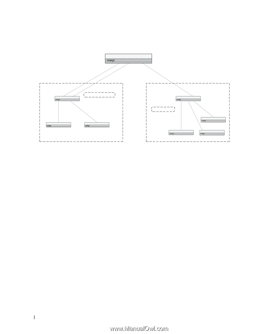
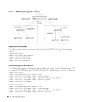
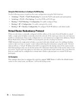
Figure 4-1. VLAN Routing Example Network Diagram Layer 3 Switch Physical Port 1/xg2 VLAN 10: 192.150.3.1 Physical Port 1/xg1 Layer 2 Switch VLAN 10 Physical Port 1/xg3 VLAN 10: 192.150.4.1 VLAN 20 Layer 2 Switch Example 1: Create Two VLANs The following code sequence shows an example of creating two VLANs with egress frame tagging enabled. console#configure console(config)#vlan database console(config-vlan)#vlan 10 console(config-vlan)#vlan 20 console(config-vlan)#exit Example 2: Configure the VLAN Members The following code sequence shows an example of adding ports to the VLANs and assigning the PVID for each port. The PVID determines the VLAN ID assigned to untagged frames received on the ports. console#configure console(config)#interface ethernet 1/g1 console(config-if-1/g1)#switchport mode general console(config-if-1/g1)#switchport general allowed vlan add 10 console(config-if-1/g1)#switchport general pvid 10 console(config-if-1/g1)#exit console#configure console(config)#interface ethernet 1/g2 console(config-if-1/g2)#switchport mode general console(config-if-1/g2)#switchport general allowed vlan add 10 console(config-if-1/g2)#switchport general pvid 10 68 Routing Configuration
-
 1
1 -
2
-
3
-
4
-
5
-
6
-
7
-
8
-
9
-
10
-
11
-
12
-
13
-
14
-
15
-
16
-
17
-
18
-
19
-
20
-
21
-
22
-
23
-
24
-
25
-
26
-
27
-
28
-
29
-
30
-
31
-
32
-
33
-
34
-
35
-
36
-
37
-
38
-
39
-
40
-
41
-
42
-
43
-
44
-
45
-
46
-
47
-
48
-
49
-
50
-
51
-
52
-
53
-
54
-
55
-
56
-
57
-
58
-
59
-
60
-
61
-
62
-
 63
63 -
 64
64 -
 65
65 -
 66
66 -
 67
67 -
 68
68 -
 69
69 -
 70
70 -
 71
71 -
 72
72 -
 73
73 -
74
-
75
-
76
-
77
-
78
-
79
-
80
-
81
-
82
-
83
-
84
-
85
-
86
-
87
-
88
-
89
-
90
-
91
-
92
-
93
-
94
-
95
-
96
-
97
-
98
-
99
-
100
-
101
-
102
-
103
-
104
-
105
-
106
-
107
-
108
-
109
-
110
-
111
-
112
-
113
-
114
-
115
-
116
-
117
-
118
-
119
-
120
-
121
-
122
-
123
-
124
-
125
-
126
-
127
-
128
-
129
-
130
-
131
-
132
-
133
-
134
-
135
-
136
-
137
-
138
-
139
-
140
-
141
-
142
-
143
-
144
-
145
-
146
-
147
-
148
-
149
-
150
-
151
-
152
-
153
-
154
-
155
-
156
-
157
-
158
 |
 |