Dell PowerEdge M520 Dell 10GbE Pass Through Module (XAUI) User Manual - Page 10
LED Indicators - drivers
 |
View all Dell PowerEdge M520 manuals
Add to My Manuals
Save this manual to your list of manuals |
Page 10 highlights
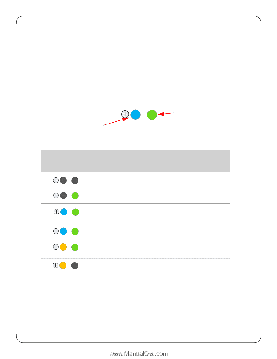
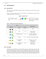
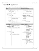
Rev 1.0 2.4 LED Indicators Installation and Basic Operation 2.4.1 System LEDs The system status LEDs indicate whether the PTM is receiving power from the chassis, and the state of the PTM. There are two system LEDs on the end of the module. The LED indications and meanings are explained in the figure and table below. Figure 5: Indicator LEDs The IO Module is on and ready when this LED is green. This LED can be blue or amber. A fault is indicated when the amber LED is blinking. See Table 3. Table 3 - PTM states and LED configurations: LED Indication Status Power OFF OFF Module Status OFF OFF Blinking Blue BLINKING BLUE ON BLUE ON Boot in Progress PTM not ready ON The CMC is identifying the newly installed PTM ON PTM is on and operating Normally ON or BLINKING ON AMBER ON or BLINKING OFF AMBER FW update is in progress or Fault in System Self-diagnosed Fault in System CMC-detected 2.4.2 Port LEDs The PTM has two I/O LEDs per port. The I/O LEDs are located on the I/O panel. The green LED, when lit, indicates that the driver is running and a valid physical connection between nodes exists. If the green LED is blinking, it indicates a problem with the physical link. The yellow LED when lit, indicates a valid data activity link, this is the logical link. The yellow LED illuminates when the network is discovered over the physical link. A valid data activity link without data transfer is des- 10
-
 1
1 -
2
-
3
-
4
-
 5
5 -
 6
6 -
 7
7 -
 8
8 -
 9
9 -
 10
10 -
 11
11 -
 12
12 -
 13
13 -
 14
14 -
 15
15 -
16
-
17
-
18
-
19
-
20
-
21
-
22
 |
 |