Dell PowerEdge M520 Dell 10GbE Pass Through Module (XAUI) User Manual - Page 21
Appendix D: Interface Connector Pinouts
 |
View all Dell PowerEdge M520 manuals
Add to My Manuals
Save this manual to your list of manuals |
Page 21 highlights
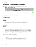
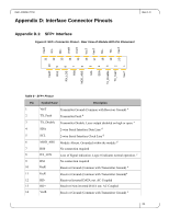
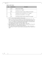
Dell -10GbE PTM Appendix D: Interface Connector Pinouts Rev 1.0 Appendix D.1: SFP+ Interface Figure 8: SFP+ Connector Pinout - Rear View of Module With Pin Placement VeeT 1 TX_Disable 3 19 TD- TX_Fault 2 2 0 VeeT SDA 4 18 TD+ SCL 5 17 VeeT 16 VccT 15 VccR 14 VeeR 13 RD+ VeeR 10 RD- 12 11 VeeR MOD_ABS 6 RS0 7 RX_LOS 8 RS1 9 Table 8 - SFP+ Pinout Pin Symbol Name Description 1 VeeT Transmitter Ground (Common with Receiver Ground) a 2 TX_Fault Transmitter Fault.b 3 TX_Disable Transmitter Disable. Laser output disabled on high or open. c 4 SDA 2-wire Serial Interface Data Line d 5 SCL 2-wire Serial Interface Clock Line d 6 MOD_ABS Module Absent. Grounded within the module d 7 RS0 No connection required 8 RX_LOS Loss of Signal indication. Logic 0 indicates normal operation. e 9 RS1 No connection required 10 VeeR Receiver Ground (Common with Transmitter Ground) a 11 VeeR Receiver Ground (Common with Transmitter Ground)a 12 RD- Receiver Inverted DATA out. AC Coupled 13 RD+ Receiver Non-inverted DATA out. AC Coupled 14 VeeR Receiver Ground (Common with Transmitter Ground) a 21
-
 1
1 -
2
-
3
-
4
-
5
-
6
-
7
-
8
-
9
-
10
-
11
-
12
-
13
-
14
-
15
-
 16
16 -
 17
17 -
 18
18 -
 19
19 -
 20
20 -
 21
21 -
 22
22
 |
 |