Dell PowerEdge M520 Dell 10 Gb Ethernet Pass Through-k for M1000e So - Page 9
Connecting the External Ports
 |
View all Dell PowerEdge M520 manuals
Add to My Manuals
Save this manual to your list of manuals |
Page 9 highlights
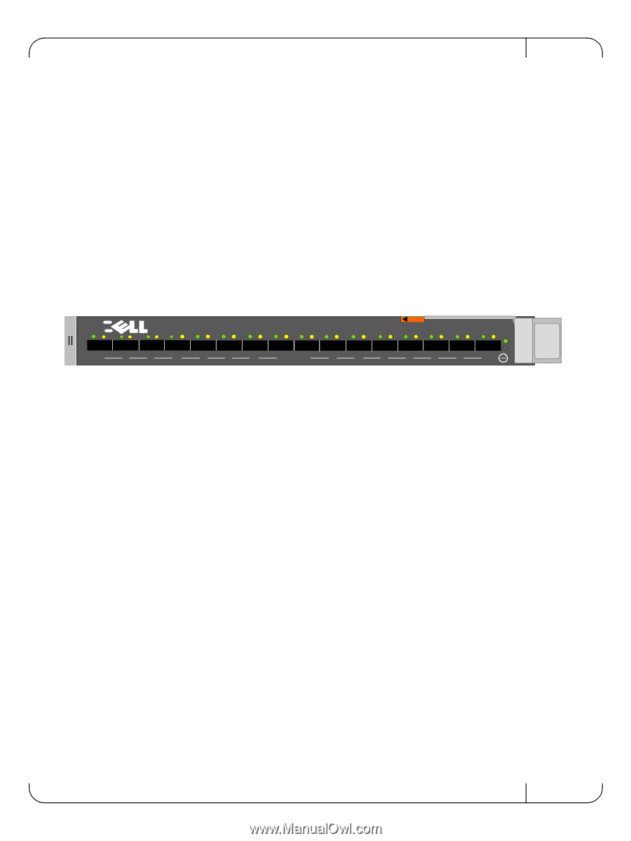
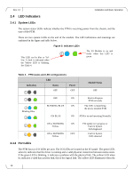
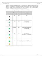
Dell -10GbE PTM Rev 1.0 The PTM supports hot-insertion into the chassis. If the PTM is inserted to a powered chassis, the power LED (green) should turn on immediately. 2.2.2 PTM Removal The PTM supports hot-removal. It may be removed when the chassis is powered on or off. The PTM must not be removed during a firmware update process. Note: Firmware update is in progress when the Yellow LED is blinking. 2.3 Connecting the External Ports The PTM front panel presents 16 SFP+ ports. Each port provides connectivity to a server with the respective number. Figure 4 shows the front panel view of the PTM. Figure 4: Dell 10Gb Ethernet Pass Through -k module Front Panel DD 10 Gb Ethernet Pass Through -k 1 2 3 4 5 6 7 8 9 10 11 12 13 14 15 16 2.3.1 10 Gigabit Ethernet SFP+ Modules The PTM supports SFP+ modules for 10 Gigabit Ethernet, with 10GBASE-SR and 10GBASE-LR PHYs. SFP+ modules must be approved for use with this PTM. Modules not approved may not work. See Supported Cables and Media Types on page 19 for lists of approved Direct Attached Copper cables (DACs) and optical modules. 2.3.2 Installation and Removal of Optical Transceiver Modules Optical transceiver modules have a locking mechanism which can be opened or closed. To insert the module into the cage: 1. Open the module's locking mechanism. 2. Make sure that the male connectors on the module aligns with the female connector inside of the cage. Also check that there is no dirt or foreign matter in the module or in the cage. 3. Insert the module into the adapter card module cage. 4. Close the locking Mechanism. To remove the module from the cage: 1. Unlock the locking mechanism by opening the handle. 2. Pull the module out of the cage. 9
-
 1
1 -
2
-
3
-
 4
4 -
 5
5 -
 6
6 -
 7
7 -
 8
8 -
 9
9 -
 10
10 -
 11
11 -
 12
12 -
 13
13 -
 14
14 -
15
-
16
-
17
-
18
-
19
-
20
-
21
-
22
-
23
 |
 |