Dell PowerEdge R420 Technical Guide - Page 51
Appendix D., System board block diagram, South, Bridge
 |
View all Dell PowerEdge R420 manuals
Add to My Manuals
Save this manual to your list of manuals |
Page 51 highlights
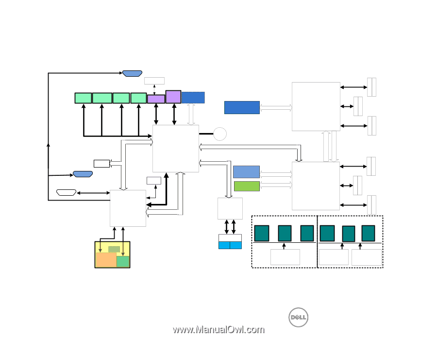
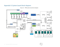
Appendix D. System board block diagram Figure 13. R420 system board block diagram Front Video DVD Int. USB 2.0 USB 2.0 IDSDM USB 2.0 (2 Front) USB 2.0 (2 Rear) SATA (1) SATA in miniSAS(4) Left* PCIe x8 Conn.(x4) Slot 1 x4 Left* PCIe x16 Conn. (option for 2rd CPU) Slot 1 x16 PCIe Gen3 x16 16GB/s LPC PCIe Gen2 x4 2GB/s USB x2 USB x2 USB x1 USB x1 SATA SATA PCIe x4 USB LPC South DMI Bridge Coin Cell x4 DMI 2GB/s TPM Rear Video USB PCIE x1 Front Panel PCIE GEN 2 x1 USB Serial Port UART LPC SPI Video USB iDRAC PCIe PCIe Gen2 x2 1GB/s Right* PCIe x16 Conn. Sxlo1t 62 PCIe x8 Conn. for int. PERC x16 PCIe Gen3 x16 16GB/s x8 PCIe Gen3 x8 8GB/s BroadCom 1GbE x 2 CPU2 QPI DMI QPI CPU1 QPI 8.0 GT/s QPI 8.0 GT/s DD II MM M M 10 DD II MM M M 10 DD II MM M M 10 DDR3 Memory (1066/1333/1600 MHz) DD II MM M M 10 DD II MM M M 10 DD II MM M M 10 MGMT SD2 MAC IDRAC Port Card FRU RJ45 12 Non-RDNT PSU System Power Conn. BP Power Conn. DVD/ TBU Power Conn. PDB+PIB for RDNT PSU System Power Conn. BP Power Conn. DVD/ TBU Power Conn. Vflash RJ45 SD Conn. (w/ PHY) Power Supply Power Supply 1 Power Supply 2 51 PowerEdge R420 Technical Guide
-
 1
1 -
2
-
3
-
4
-
5
-
6
-
7
-
8
-
9
-
10
-
11
-
12
-
13
-
14
-
15
-
16
-
17
-
18
-
19
-
20
-
21
-
22
-
23
-
24
-
25
-
26
-
27
-
28
-
29
-
30
-
31
-
32
-
33
-
34
-
35
-
36
-
37
-
38
-
39
-
40
-
41
-
42
-
43
-
44
-
45
-
 46
46 -
 47
47 -
 48
48 -
 49
49 -
 50
50 -
 51
51
 |
 |