Dell PowerEdge T110 II Owner's Manual
Dell PowerEdge T110 II Manual
 |
View all Dell PowerEdge T110 II manuals
Add to My Manuals
Save this manual to your list of manuals |
Dell PowerEdge T110 II manual content summary:
- Dell PowerEdge T110 II | Owner's Manual - Page 1
Dell PowerEdge T110 II Systems Owner's Manual Regulatory Model E11S Series Regulatory Type E11S002 - Dell PowerEdge T110 II | Owner's Manual - Page 2
indicates potential damage to hardware or loss of data if instructions are not followed. WARNING: A WARNING indicates a potential for Dell Inc. is strictly forbidden. Trademarks used in this text: Dell™, the DELL logo, PowerEdge™ are trademarks of Dell Inc. Microsoft®, Windows®, and Windows Server - Dell PowerEdge T110 II | Owner's Manual - Page 3
Accessing System Features During Startup 9 Front-Panel Features and Indicators 10 Back-Panel Features and Indicators 12 Guidelines for Connecting External Devices 13 NIC Indicator Codes 14 Diagnostic Lights 15 System Messages 17 Warning Messages 20 Diagnostics Messages 20 Alert Messages 20 - Dell PowerEdge T110 II | Owner's Manual - Page 4
Main Screen 25 Memory Settings Screen 27 Processor Settings Screen 27 SATA Settings Screen 28 Boot Settings Screen 29 Integrated Devices Screen 29 PCI IRQ Assignments Screen 30 Serial Communication Screen 31 Power Management Screen 32 System Security Screen 33 Exit Screen 35 Entering the - Dell PowerEdge T110 II | Owner's Manual - Page 5
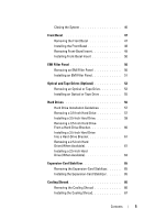
Insert 49 Installing Front-Bezel Insert 50 EMI Filler Panel 50 Removing an EMI Filler Panel 50 Installing an EMI Filler Panel 51 Optical and Tape Drives (Optional 52 Removing an Optical or Tape Drive 52 Installing an Optical or Tape Drive 55 Hard Drives 56 Hard Drive Installation Guidelines - Dell PowerEdge T110 II | Owner's Manual - Page 6
Power Supply 86 Removing the Power Supply 86 Installing the Power Supply 87 Internal USB Memory Key 88 Chassis Intrusion Switch 89 Removing the Chassis Intrusion Switch 89 Installing the Chassis Intrusion Switch 90 Control Panel Assembly 91 Removing the Control Panel Assembly 91 Installing - Dell PowerEdge T110 II | Owner's Manual - Page 7
the System Battery 104 Troubleshooting Power Supply 105 Troubleshooting System Cooling Problems 105 Troubleshooting Cooling Fan 106 Troubleshooting System Memory 107 Troubleshooting an Internal USB Key 108 Troubleshooting an Optical Drive 109 Troubleshooting a Tape Backup Unit 110 - Dell PowerEdge T110 II | Owner's Manual - Page 8
a Hard Drive 111 Troubleshooting Expansion Cards 112 Troubleshooting the Processor 113 5 Running the System Diagnostics 115 Using Online Diagnostics 115 Embedded System Diagnostics Features 115 When to Use the Embedded System Diagnostics . . . . . 116 Running the Embedded System Diagnostics - Dell PowerEdge T110 II | Owner's Manual - Page 9
Setup Program and Boot Manager" on page 23. Enters System Services, which opens the Dell Unified Server Configurator (USC). The Dell USC allows you to access utilities such as embedded system diagnostics. For more information, see the Dell USC documentation. Enters the BIOS Boot - Dell PowerEdge T110 II | Owner's Manual - Page 10
and Indicators Figure 1-1. Front-Panel Features and Indicators 1 2 3 4 7 6 Item Indicator, Button, or Icon Connector 1 Power-on indicator, power button 5 Description The power-on indicator lights when the system power is on. The power button controls the DC power supply output to the - Dell PowerEdge T110 II | Owner's Manual - Page 11
a system fault is detected. The hard drive activity indicator lights up when the hard drive is in use. Connect USB devices to the system. The ports are USB 2.0-compliant. The four diagnostic indicator lights display error codes during system startup. See "Diagnostic Lights" on page 15. One optional - Dell PowerEdge T110 II | Owner's Manual - Page 12
Back-Panel Features and Indicators 1 2 3 4 5 6 7 8 9 10 Item Indicator, Button, or Icon Connector 1 Padlock ring 2 Security cable slot 3 Power supply 4 Cable clasp Description Locks the cover release latch. Connects a cable lock to the system. 305 W power supply. Secures the power cable - Dell PowerEdge T110 II | Owner's Manual - Page 13
for the device specifies otherwise). • Ensure that the appropriate driver for the attached device has been installed on the system. • If necessary to enable ports on your system, use the System Setup program. See "Using the System Setup Program and Boot Manager" on page 23. About Your System 13 - Dell PowerEdge T110 II | Owner's Manual - Page 14
NIC Indicator Codes Figure 1-3. NIC Indicator Codes 1 2 1 link indicator 2 activity indicator Indicator Link and activity indicators are off Link indicator is green Link indicator is amber Activity indicator is green blinking Indicator Code The NIC is not connected to the network. The NIC is - Dell PowerEdge T110 II | Owner's Manual - Page 15
Diagnostic Lights The four diagnostic indicator lights on the system front panel display error codes during system startup. Table 1-1 lists the causes and possible corrective actions associated with these codes. A highlighted circle indicates the light is on; a non-highlighted circle indicates the - Dell PowerEdge T110 II | Owner's Manual - Page 16
connected. See "Hard Drives" on page 56 for information on the drives installed in your system. See "Troubleshooting a USB Device" on page 100. See "Troubleshooting System Memory" on page 107. See "Getting Help" on page 123. Memory configuration See "Troubleshooting System error. Memory" on page - Dell PowerEdge T110 II | Owner's Manual - Page 17
is installed in the clear setting. CMOS has been cleared. Move the NVRAM_CLR jumper to the default position (pins 3 and 5). See Figure 6-1 for jumper location. Restart the system and re-enter the BIOS settings. See "Using the System Setup Program and Boot Manager" on page 23. Invalid configuration - Dell PowerEdge T110 II | Owner's Manual - Page 18
Module Installation Guidelines" on page 73. Use a bootable USB key, CD, or hard drive. If the problem persists, see "Troubleshooting a USB Device" on page 100, "Troubleshooting an Optical Drive" on page 109, and "Troubleshooting a Hard Drive" on page 111. See "Using the System Setup Program and Boot - Dell PowerEdge T110 II | Owner's Manual - Page 19
-bit errors were detected and replace the faulty memory module. See "Troubleshooting System Memory" on page 107. Time-of-day not Incorrect Time or Date set - please run settings; faulty system SETUP program. battery. Check the Time and Date settings. See "Using the System Setup Program and Boot - Dell PowerEdge T110 II | Owner's Manual - Page 20
for processor n. Micro code update failed. Update the BIOS firmware. See "Getting Help" on page 123. NOTE: For the full name of an abbreviation or acronym used in this table, see the Glossary on support.dell.com/manuals. Warning Messages A warning message alerts you to a possible problem and - Dell PowerEdge T110 II | Owner's Manual - Page 21
Started Guide provides an configuring and managing your system, including those pertaining to the operating system, system management software, system updates, and system components that you purchased with your system. NOTE: Always check for updates on support.dell.com/manuals and read the updates - Dell PowerEdge T110 II | Owner's Manual - Page 22
22 About Your System - Dell PowerEdge T110 II | Owner's Manual - Page 23
power management thresholds • Manage system security Choosing the System Boot Mode The System Setup program also enables you to specify the boot mode for installing your operating system: • BIOS boot mode (the default) is the standard BIOS-level boot interface. • UEFI boot mode is an enhanced 64-bit - Dell PowerEdge T110 II | Owner's Manual - Page 24
is booting, make a note of the message. See "System Messages" on page 17 for an explanation of the message and suggestions for correcting errors. NOTE: After installing a memory upgrade, it is normal for your system to display a message the first time you start your system. Using the System Setup - Dell PowerEdge T110 II | Owner's Manual - Page 25
Option System Time System Date Memory Settings Description Sets the time on the system's internal clock. Sets the date on the system's internal calendar. Displays information related to installed memory. See "Memory Settings Screen" on page 27. Using the System Setup Program and Boot Manager 25 - Dell PowerEdge T110 II | Owner's Manual - Page 26
Communication Screen" on page 31. Enables you to manage power usage of the processor, fans, and memory modules with preconfigured or customized settings. See "Power Management Screen" on page 32. Displays a screen to configure the system password and setup password features. See "System Security - Dell PowerEdge T110 II | Owner's Manual - Page 27
at system boot. Options are Enabled and Disabled. Processor Settings Screen Option 64-bit Core Speed Bus Speed Description Specifies if the processor supports 64-bit extensions. Displays the processor clock speed. Displays the processor bus speed. Using the System Setup Program and Boot Manager - Dell PowerEdge T110 II | Owner's Manual - Page 28
Off, ATA, AHCI, or RAID modes. Auto enables BIOS support for the device attached to SATA port A. Off disables BIOS support for the device. Auto enables BIOS support for the device attached to SATA port B. Off disables BIOS support for the device. 28 Using the System Setup Program and Boot Manager - Dell PowerEdge T110 II | Owner's Manual - Page 29
field to BIOS allows compatibility with non-UEFI operating systems. NOTE: Setting this field to UEFI disables the Boot Sequence, Hard-Disk Drive Sequence, and USB Flash Drive Emulation Type fields. If this field is enabled and the system has failed to boot, the system re-attempts to boot after 30 - Dell PowerEdge T110 II | Owner's Manual - Page 30
of the Advanced Configuration and Power Interface (ACPI) 3.0b specification. Enables or disables BIOS support for the integrated video controller. NOTE: This field can be disabled only if an add-in video card is present. If this field is disabled, remote access features such as virtual KVM are not - Dell PowerEdge T110 II | Owner's Manual - Page 31
2 can be used for SOL. To use console redirection by SOL, configure the same port address for console redirection and the serial device. Failsafe Baud Boot (Enabled default) Enables or disables BIOS console redirection when the operating system is loaded. Using the System Setup Program and Boot - Dell PowerEdge T110 II | Owner's Manual - Page 32
all but the Custom setting, the BIOS pre-configures the power settings on this screen as follows: • OS Control sets the CPU power to OS DBPM, the fan power to Minimum Power, and the memory power to Maximum Performance. In this setting, all processor performance information is passed from the system - Dell PowerEdge T110 II | Owner's Manual - Page 33
system and bypasses pre-boot measurements. When set to Disabled, the TPM is disabled.When set to Deactivated, the TPM is deactivated. When set to Activate, the TPM is enabled to default settings. When Password" on page 38 for more information. Using the System Setup Program and Boot Manager 33 - Dell PowerEdge T110 II | Owner's Manual - Page 34
, the button can only turn on system power. Use the NMI button only if directed to do so by qualified support personnel or by the operating system's documentation. Pressing this button halts the operating system and displays a diagnostic screen. Enables or disables the NMI feature. Determines how - Dell PowerEdge T110 II | Owner's Manual - Page 35
, Microsoft Windows Server 2008 x64 version) to be installed from the UEFI boot mode. DOS and 32-bit operating systems can only be installed from the BIOS boot mode. NOTE: The Boot Mode must be set to UEFI in the System Setup program to access the Boot Manager. The Boot Manager enables you to: • Add - Dell PowerEdge T110 II | Owner's Manual - Page 36
use and press Enter. Enables you to add, delete, enable, or disable boot options; change boot order; or execute a one-time boot option. Enables you to access the System Setup program, System Services (Dell Unified Server Configurator [USC]), Diagnostics, and BIOS-level boot options. 36 Using the - Dell PowerEdge T110 II | Owner's Manual - Page 37
Adds a new boot option. Deletes an existing boot option. Disables and enables a boot option in the boot option list. Sets a one-time boot option not included in the boot option list. Sets the order of the boot option list. System Utilities Screen Option System Setup System Services Reset - Dell PowerEdge T110 II | Owner's Manual - Page 38
Before assigning a system password, enter the System Setup program and check the System Password option. When a system password is assigned, System Password is Enabled. If Password Status is Unlocked, you can , placeholders appear in the field. 38 Using the System Setup Program and Boot Manager - Dell PowerEdge T110 II | Owner's Manual - Page 39
press . System Password changes to Enabled. Exit the System Setup program and begin using your system. assigned a setup password (see "Using the Setup Password" on page 40), the system accepts your setup password the system displays an error message that the system has halted and will shut - Dell PowerEdge T110 II | Owner's Manual - Page 40
> to access the setup password window. Press twice to clear the existing setup password. 3 The setting changes to Not Enabled. 4 To assign a new setup password, perform the steps in "Assigning a Setup Password" on page 40. Using the Setup Password Assigning a Setup Password You can assign - Dell PowerEdge T110 II | Owner's Manual - Page 41
. The following features of Dell USC are supported on systems with Baseboard Management Controller (BMC): • Installing an operating system • Running diagnostics to validate the memory, I/O devices, processor, physical disks, and other peripherals Using the System Setup Program and Boot Manager 41 - Dell PowerEdge T110 II | Owner's Manual - Page 42
hardware and firmware, and deploying the operating system, see the Unified Server Configurator documentation at support.dell.com/manuals. Baseboard Management Controller Configuration The BMC enables configuring, monitoring, and recovery of systems remotely. The BMC provides the following - Dell PowerEdge T110 II | Owner's Manual - Page 43
3 Installing System Components Recommended Tools You may need the following items to perform the procedures in this section: • Key to the system keylock • #2 Phillips screwdriver • Wrist grounding strap Installing System Components 43 - Dell PowerEdge T110 II | Owner's Manual - Page 44
support team. Damage due to servicing that is not authorized by Dell is not covered by your warranty. Read and follow the safety instructions that came with the product. Figure 3-1. Inside the System 1 2 3 8 7 6 1 power supply 3 cooling shroud 5 heat sink 7 tape drive (optional) 4 5 2 chassis - Dell PowerEdge T110 II | Owner's Manual - Page 45
only perform troubleshooting and simple repairs as authorized in your product documentation, or as directed by the online or telephone service and support team. Damage due to servicing that is not authorized by Dell is not covered by your warranty. Read and follow the safety instructions that came - Dell PowerEdge T110 II | Owner's Manual - Page 46
Figure 3-2. Opening and Closing the System 1 1 release tab Closing the System 1 Align the cover with the slots on the bottom of the chassis. See Figure 3-2. 2 Press down on the cover until the cover release tab snaps into place. 3 Place the system upright on a flat, stable surface. 4 Reconnect the - Dell PowerEdge T110 II | Owner's Manual - Page 47
only perform troubleshooting and simple repairs as authorized in your product documentation, or as directed by the online or telephone service and support team. Damage due to servicing that is not authorized by Dell is not covered by your warranty. Read and follow the safety instructions that came - Dell PowerEdge T110 II | Owner's Manual - Page 48
support team. Damage due to servicing that is not authorized by Dell is not covered by your warranty. Read and follow the safety instructions that came with the product. 1 Align the tabs on the front bezel with the slots on the chassis. See Figure 3-3. 2 Snap the bezel into place. 48 Installing - Dell PowerEdge T110 II | Owner's Manual - Page 49
online or telephone service and support team. Damage due to servicing that is not authorized by Dell is not covered by your warranty. Read and follow the safety instructions that came with the product. NOTE: Before installing a drive in one or more of the front drive bays, remove the corresponding - Dell PowerEdge T110 II | Owner's Manual - Page 50
only perform troubleshooting and simple repairs as authorized in your product documentation, or as directed by the online or telephone service and support team. Damage due to servicing that is not authorized by Dell is not covered by your warranty. Read and follow the safety instructions that came - Dell PowerEdge T110 II | Owner's Manual - Page 51
by the online or telephone service and support team. Damage due to servicing that is not authorized by Dell is not covered by your warranty. Read and follow the safety instructions that came with the product. 1 Align the screws on the EMI filler panel with the slots in the chassis and slide the EMI - Dell PowerEdge T110 II | Owner's Manual - Page 52
only perform troubleshooting and simple repairs as authorized in your product documentation, or as directed by the online or telephone service and support team. Damage due to servicing that is not authorized by Dell is not covered by your warranty. Read and follow the safety instructions that came - Dell PowerEdge T110 II | Owner's Manual - Page 53
Figure 3-6. Removing and Installing a Tape Drive (SAS Connection) 1 5 4 2 1 power/data cable 3 drive bay screw slots 5 tape drive shoulder screws (3) 3 2 drive release latch 4 tape drive Installing System Components 53 - Dell PowerEdge T110 II | Owner's Manual - Page 54
1 power/data cable 3 drive bay screw slots 5 optical drive shoulder screws (3) 2 drive release latch 4 optical drive 6 If you are installing another drive in the bay, see "Installing an Optical or Tape Drive" on page 55. 7 If the drive is being permanently removed, install an insert on the front - Dell PowerEdge T110 II | Owner's Manual - Page 55
by the online or telephone service and support team. Damage due to servicing that is not authorized by Dell is not covered by your warranty. Read and follow the safety instructions that came with the product. 1 Unpack the drive and prepare it for installation. For instructions, see the documentation - Dell PowerEdge T110 II | Owner's Manual - Page 56
Figure 3-8. Installing Drive Shoulder Screws 1 1 shoulder screws (3)* *Screws are supplied along with the drives ordered from Dell. 8 Gently slide the drive into the bay until it clicks into place. 9 Attach the SAS cable (tape drive) or SATA power cable (optical drive) to the drive. Ensure that - Dell PowerEdge T110 II | Owner's Manual - Page 57
are not supported. Hard Drive Installation Guidelines Your system supports up to four 3.5-inch or six 2.5-inch hard drives in internal drive bays. Removing a 3.5-Inch Hard Drive CAUTION: Many repairs may only be done by a certified service technician. You should only perform troubleshooting and - Dell PowerEdge T110 II | Owner's Manual - Page 58
and Installing a 3.5-Inch Hard Drive 2 3 1 4 1 hard drive 3 tabs (2) 2 power/data cable 4 hard drive bracket NOTE: If you are not replacing the hard drive, remove the drive from the drive bracket (see Figure 3-11) and insert the empty bracket back into the drive bay. 5 Detach the hard-drive - Dell PowerEdge T110 II | Owner's Manual - Page 59
Installing a 3.5-Inch Hard Drive CAUTION: Many repairs may only be done by a certified service technician. You should only perform troubleshooting and simple repairs as authorized in your product documentation, or as directed by the online or telephone service and support team. Damage due to - Dell PowerEdge T110 II | Owner's Manual - Page 60
Setup program and ensure that the hard drive's controller is enabled. See "Entering the System Setup Program" on page 24. 9 Exit the System Setup program and reboot the system. 10 Partition and logically format the drive. See the documentation that came with the drive for instructions on installing - Dell PowerEdge T110 II | Owner's Manual - Page 61
Hard Drive (When Available) CAUTION: Many repairs may only be done by a certified service technician. You should only perform troubleshooting and simple repairs as authorized in your product documentation, or as directed by the online or telephone service and support team. Damage due to servicing - Dell PowerEdge T110 II | Owner's Manual - Page 62
up and out of the bay. See Figure 3-12. Figure 3-12. Removing a 2.5-Inch Hard-Drive Carrier 1 2 3 1 hard drive 3 blue tabs (4) 2 hard-drive carrier 5 Remove the four screws on the two sides of the hard-drive carrier and pull out the hard drive. See Figure 3-13. 62 Installing System Components - Dell PowerEdge T110 II | Owner's Manual - Page 63
46. Installing a 2.5-Inch Hard Drive (When Available) CAUTION: Many repairs may only be done by a certified service technician. You should only perform troubleshooting and simple repairs as authorized in your product documentation, or as directed by the online or telephone service and support team - Dell PowerEdge T110 II | Owner's Manual - Page 64
Cable to the Hard Drive 1 2 1 power/data cables 2 hard drives 8 Close the system. See "Closing the System" on page 46. 9 Enter the System Setup program and ensure that the hard drive's controller is enabled. See "Entering the System Setup Program" on page 24. 64 Installing System Components - Dell PowerEdge T110 II | Owner's Manual - Page 65
or telephone service and support team. Damage due to servicing that is not authorized by Dell is not covered by your warranty. Read and follow the safety instructions that came with the product. 1 Slide the edge of the expansion-card stabilizer into the slots in the cooling shroud and chassis until - Dell PowerEdge T110 II | Owner's Manual - Page 66
only perform troubleshooting and simple repairs as authorized in your product documentation, or as directed by the online or telephone service and support team. Damage due to servicing that is not authorized by Dell is not covered by your warranty. Read and follow the safety instructions that came - Dell PowerEdge T110 II | Owner's Manual - Page 67
only perform troubleshooting and simple repairs as authorized in your product documentation, or as directed by the online or telephone service and support team. Damage due to servicing that is not authorized by Dell is not covered by your warranty. Read and follow the safety instructions that came - Dell PowerEdge T110 II | Owner's Manual - Page 68
Expansion Card Installation Guidelines Your system supports up to four PCIe Generation 2 cards. To identify the expansion slots, see Figure 6-1. Observe the following notes and guidelines regarding the expansion-card slots: • The expansion-card slots are not hot-swappable. • PCI Express Generation - Dell PowerEdge T110 II | Owner's Manual - Page 69
card. You can install either of the above mentioned RAID cards in slot 1. The size of the expansion card connectors for the PCI x8 card is PCI x8. Removing an Expansion Card CAUTION: Many repairs may only be done by a certified service technician. You should only perform troubleshooting and simple - Dell PowerEdge T110 II | Owner's Manual - Page 70
the expansion card stabilizer. See "Installing the Expansion-Card Stabilizer" on page 65. 9 Close the system. See "Closing the System" on page 46. 10 Reconnect the system and peripherals to their power sources, and turn them on. 11 Remove the card's device driver from the operating system. 70 - Dell PowerEdge T110 II | Owner's Manual - Page 71
only perform troubleshooting and simple repairs as authorized in your product documentation, or as directed by the online or telephone service and support team. Damage due to servicing that is not authorized by Dell is not covered by your warranty. Read and follow the safety instructions that came - Dell PowerEdge T110 II | Owner's Manual - Page 72
Filler brackets must be installed over empty expansion-card slots to maintain FCC certification of installation instructions in the documentation for your SAS controller card. Install the card in the expansion card connector (see "Installing an Expansion Card" on page 71), and connect the hard-drive - Dell PowerEdge T110 II | Owner's Manual - Page 73
the speed of the slowest installed memory module(s). Mode-Specific Guidelines Your system supports both single-channel and dual-channel mode. A minimal single-channel configuration of one 1 GB memory module is also supported in this mode. Table 3-2 shows sample memory configurations that follow the - Dell PowerEdge T110 II | Owner's Manual - Page 74
Table 3-2. Sample UDIMM Memory Configurations Memory Module Size 1 Memory Sockets 2 1 GB 2 GB 4 GB 8 GB 3 4 X X X X X X X X X X X X X X X X X X X X X X X X X X X X Single Processor Physical Memory (GB) 1 2 4 2 4 8 4 8 16 8 16 32 74 Installing System Components - Dell PowerEdge T110 II | Owner's Manual - Page 75
or telephone service and support team. Damage due to servicing that is not authorized by Dell is not covered by your warranty. Read and follow the safety instructions that came with the product. CAUTION: To ensure proper system cooling, memory-module blanks must be installed in any memory socket - Dell PowerEdge T110 II | Owner's Manual - Page 76
or telephone service and support team. Damage due to servicing that is not authorized by Dell is not covered by your warranty. Read and follow the safety instructions that came with the product. CAUTION: To ensure proper system cooling, memory-module blanks must be installed in any memory socket - Dell PowerEdge T110 II | Owner's Manual - Page 77
page 67. 14 Close the system. See "Closing the System" on page 46. 15 Reconnect the system and peripherals to their power sources, and turn them on. 16 Press to enter the System Setup program, and check the System Memory setting on the main System Setup screen. Installing System Components 77 - Dell PowerEdge T110 II | Owner's Manual - Page 78
system BIOS version from support.dell.com and follow the instructions included in the compressed download file to install the update on your system. 2 Turn off the system, including any attached peripherals, and disconnect the system from the electrical outlet. When disconnected from AC power, press - Dell PowerEdge T110 II | Owner's Manual - Page 79
and set the heat sink aside upside down (thermal grease side facing up). Figure 3-18. Installing and Removing the Heat Sink 1 2 1 heat sink 2 heat-sink retention screws (4) CAUTION: The processor is held in its socket under strong pressure. Be aware that the release lever can spring up suddenly - Dell PowerEdge T110 II | Owner's Manual - Page 80
19. 11 Use the tab on the processor shield to rotate shield upward and out of the way. See Figure 3-19. Figure 3-19. Removing a Processor 2 1 3 1 socket-release lever 3 notches in processor (2) 5 ZIF socket 4 5 6 2 processor 4 processor shield 6 socket keys (2) 80 Installing System Components - Dell PowerEdge T110 II | Owner's Manual - Page 81
only perform troubleshooting and simple repairs as authorized in your product documentation, or as directed by the online or telephone service and support team. Damage due to servicing that is not authorized by Dell is not covered by your warranty. Read and follow the safety instructions that came - Dell PowerEdge T110 II | Owner's Manual - Page 82
only perform troubleshooting and simple repairs as authorized in your product documentation, or as directed by the online or telephone service and support team. Damage due to servicing that is not authorized by Dell is not covered by your warranty. Read and follow the safety instructions that came - Dell PowerEdge T110 II | Owner's Manual - Page 83
the online or telephone service and support team. Damage due to servicing that is not authorized by Dell is not covered by your warranty. Read and follow the safety instructions that came with the product. 1 Align the tabs on the system fan with the securing slots on the chassis. 2 Slide the system - Dell PowerEdge T110 II | Owner's Manual - Page 84
only perform troubleshooting and simple repairs as authorized in your product documentation, or as directed by the online or telephone service and support team. Damage due to servicing that is not authorized by Dell is not covered by your warranty. Read and follow the safety instructions that came - Dell PowerEdge T110 II | Owner's Manual - Page 85
Enter the System Setup program to confirm that the battery is operating properly. See "Using the System Setup Program and Boot Manager" on page 23. 8 Enter the correct time and date in the System Setup program's Time and Date fields. 9 Exit the System Setup program. Installing System Components 85 - Dell PowerEdge T110 II | Owner's Manual - Page 86
the power supply to the back panel. 8 Press the power-supply release tab down and slide the power supply toward the front of the system. 9 Lift the power-supply out of the chassis. See Figure 3-22. 10 Remove the cable clip and set it aside to attach to the new power supply. 86 Installing System - Dell PowerEdge T110 II | Owner's Manual - Page 87
support team. Damage due to servicing that is not authorized by Dell is not covered by your warranty. Read and follow the safety instructions that came with the product. 1 Attach the cable clip to the new power supply. 2 Align the power supply mounting holes with the mounting holes on the back panel - Dell PowerEdge T110 II | Owner's Manual - Page 88
" on page 46. Internal USB Memory Key An optional USB memory key installed inside your system can be used as a boot device, security key, or mass storage device. CAUTION: Many repairs may only be done by a certified service technician. You should only perform troubleshooting and simple repairs as - Dell PowerEdge T110 II | Owner's Manual - Page 89
3-23. Removing and Installing a USB Memory Key 1 2 1 USB memory key 2 USB memory key connector Chassis Intrusion Switch Removing the Chassis Intrusion Switch CAUTION: Many repairs may only be done by a certified service technician. You should only perform troubleshooting and simple repairs as - Dell PowerEdge T110 II | Owner's Manual - Page 90
only perform troubleshooting and simple repairs as authorized in your product documentation, or as directed by the online or telephone service and support team. Damage due to servicing that is not authorized by Dell is not covered by your warranty. Read and follow the safety instructions that came - Dell PowerEdge T110 II | Owner's Manual - Page 91
only perform troubleshooting and simple repairs as authorized in your product documentation, or as directed by the online or telephone service and support team. Damage due to servicing that is not authorized by Dell is not covered by your warranty. Read and follow the safety instructions that came - Dell PowerEdge T110 II | Owner's Manual - Page 92
Figure 3-25. Removing and Installing the Link Bracket Lock 1 2 1 screw 2 link bracket lock 6 Remove the mounting screw holding the control panel assembly to the chassis. See Figure 3-26. 7 Move the control panel assembly toward the back of the system and lift it out of the system. CAUTION: Do not - Dell PowerEdge T110 II | Owner's Manual - Page 93
on the chassis and secure it with the screw. See Figure 3-26. 3 Secure the link bracket lock by replacing the screw. See Figure 3-26. 4 Secure the control panel cable through the clips beneath the optional tape or optical drive and on the side of the power supply unit. Installing System Components - Dell PowerEdge T110 II | Owner's Manual - Page 94
only perform troubleshooting and simple repairs as authorized in your product documentation, or as directed by the online or telephone service and support team. Damage due to servicing that is not authorized by Dell is not covered by your warranty. Read and follow the safety instructions that came - Dell PowerEdge T110 II | Owner's Manual - Page 95
toward the front end of the chassis. CAUTION: Do not lift the system board by grasping a memory module, processor, or other components. 11 Grasp the system board by the edges of the system board and lift the system board out of the chassis. See Figure 3-27. Figure 3-27. Removing and Installing the - Dell PowerEdge T110 II | Owner's Manual - Page 96
and support team. Damage due to servicing that is not authorized by Dell is not covered by your warranty. Read and follow the safety instructions that came with the product. 1 Unpack the new system board. 2 Remove the labels from the processor shield and affix them to the system identification panel - Dell PowerEdge T110 II | Owner's Manual - Page 97
the Cooling Shroud" on page 67. 14 Replace the expansion-card stabilizer. See "Installing the Expansion-Card Stabilizer" on page 65. 15 Close the system. See "Closing the System" on page 46. 16 Reconnect the system to its electrical - Dell PowerEdge T110 II | Owner's Manual - Page 98
98 Installing System Components - Dell PowerEdge T110 II | Owner's Manual - Page 99
and support team. Damage due to servicing that is not authorized by Dell is not covered by your warranty. Read and follow the safety instructions that came with the product. Troubleshooting System Startup Failure If your system halts during startup prior to video output, especially after installing - Dell PowerEdge T110 II | Owner's Manual - Page 100
Setup program, and check if the nonfunctioning USB ports are enabled. 4 Replace the keyboard/mouse with another working keyboard/mouse. 5 If the problem is resolved, replace the faulty keyboard/mouse. 6 If the problem is not resolved, proceed to the next step to begin troubleshooting the other USB - Dell PowerEdge T110 II | Owner's Manual - Page 101
10 If a device causes the same problem, power down the device, replace the USB cable, and power up the device. If the problem persists, replace the device. If all troubleshooting fails, see "Getting Help" on page 123. Troubleshooting a Serial I/O Device 1 Turn off the system and any peripheral - Dell PowerEdge T110 II | Owner's Manual - Page 102
. See "Installing System Components" on page 43. • Hard drives • USB memory key • Cooling shroud and expansion-card stabilizer • Expansion cards • Power supply • Cooling fan • Processor and heat sink • Memory modules 4 Let the system dry thoroughly for at least 24 hours. 102 Troubleshooting Your - Dell PowerEdge T110 II | Owner's Manual - Page 103
installed: • Cooling shroud and expansion-card stabilizer • Expansion cards • Power supply • Cooling fan • Processor and heat sink • Memory modules • Hard-drive carriers 4 Ensure that all cables are properly connected. 5 Close the system. See "Closing the System" on page 46. Troubleshooting - Dell PowerEdge T110 II | Owner's Manual - Page 104
only perform troubleshooting and simple repairs as authorized in your product documentation, or as directed by the online or telephone service and support team. Damage due to servicing that is not authorized by Dell is not covered by your warranty. Read and follow the safety instructions that came - Dell PowerEdge T110 II | Owner's Manual - Page 105
service and support team. Damage due to servicing that is not authorized by Dell is not covered by your warranty. Read and follow the safety instructions that came with the product. 1 Reseat the power supply by removing and reinstalling it. See "Removing the Power Supply" on page 86 and "Installing - Dell PowerEdge T110 II | Owner's Manual - Page 106
only perform troubleshooting and simple repairs as authorized in your product documentation, or as directed by the online or telephone service and support team. Damage due to servicing that is not authorized by Dell is not covered by your warranty. Read and follow the safety instructions that came - Dell PowerEdge T110 II | Owner's Manual - Page 107
or as directed by the online or telephone service and support team. Damage due to servicing that is not authorized by Dell is not covered by your warranty. Read and follow the safety instructions that came with the product. NOTE: Invalid memory configurations can cause your system to halt at startup - Dell PowerEdge T110 II | Owner's Manual - Page 108
the diagnostic indicators on the front of the system. 16 If the memory problem is still indicated, repeat step 12 through step 15 for each memory module installed. If the problem persists after all memory modules have been checked, see "Getting Help" on page 123. Troubleshooting an Internal USB Key - Dell PowerEdge T110 II | Owner's Manual - Page 109
instructions that came with the product. 1 Try using a different CD or DVD. 2 Enter the System Setup program and ensure that the integrated SATA controller and the drive's SATA port are enabled. See "Using the System Setup Program and Boot Manager" on page 23. 3 Run the appropriate online diagnostic - Dell PowerEdge T110 II | Owner's Manual - Page 110
support team. Damage due to servicing that is not authorized by Dell is not covered by your warranty. Read and follow the safety instructions that came with the product. 1 Try using a different tape cartridge. 2 Ensure that the device drivers for the tape backup unit are installed and are configured - Dell PowerEdge T110 II | Owner's Manual - Page 111
and support team. Damage due to servicing that is not authorized by Dell is not covered by your warranty. Read and follow the safety instructions that came with the product. CAUTION: This troubleshooting procedure can destroy data stored on the hard drive. Before you proceed, back up all files on - Dell PowerEdge T110 II | Owner's Manual - Page 112
or as directed by the online or telephone service and support team. Damage due to servicing that is not authorized by Dell is not covered by your warranty. Read and follow the safety instructions that came with the product. NOTE: When troubleshooting an expansion card, see the documentation for your - Dell PowerEdge T110 II | Owner's Manual - Page 113
only perform troubleshooting and simple repairs as authorized in your product documentation, or as directed by the online or telephone service and support team. Damage due to servicing that is not authorized by Dell is not covered by your warranty. Read and follow the safety instructions that came - Dell PowerEdge T110 II | Owner's Manual - Page 114
114 Troubleshooting Your System - Dell PowerEdge T110 II | Owner's Manual - Page 115
as hard drives, physical memory, communications and printer ports, NICs, CMOS, and more. If you are unable to identify the problem using the online diagnostics, then use the embedded system diagnostics. The files required to run the online diagnostics for systems running supported Microsoft Windows - Dell PowerEdge T110 II | Owner's Manual - Page 116
problem. Running the Embedded System Diagnostics The embedded system diagnostics program is run from the Dell USC screen. CAUTION: Use the embedded system diagnostics to test only your system. Using this program with other systems may cause invalid results or error messages. 1 As the system boots - Dell PowerEdge T110 II | Owner's Manual - Page 117
test results. Selecting Devices for Testing The left side of the Customize window lists devices that can be tested. Click (+) next to a file pathname-Enables you to specify the USB memory key where the test log file is saved. You cannot save the file to a hard drive. Running the System Diagnostics - Dell PowerEdge T110 II | Owner's Manual - Page 118
-Displays the test that ran and the result. • Errors-Displays any errors that occurred during the test. • Help-Displays information about the currently selected device, component, or test. • Configuration-Displays basic configuration information about the currently selected device. • Parameters - Dell PowerEdge T110 II | Owner's Manual - Page 119
Description (default) The password feature is enabled (pins 2-4) NVRAM_CLR The password feature is disabled (pins 4-6) (default) The configuration settings are retained at system boot (pins 3-5) The configuration settings are cleared at the next system boot (pins 1-3) Jumpers and Connectors 119 - Dell PowerEdge T110 II | Owner's Manual - Page 120
26 10 25 24 11 23 22 21 20 12 19 18 13 17 16 15 14 Table 6-2. System Board Jumpers and Connectors Item Connector 1 USB 2 SATA_F eSATA 3 COM 4 VGA Description USB connectors (4) eSATA connector Serial connector Video connector 120 Jumpers and Connectors - Dell PowerEdge T110 II | Owner's Manual - Page 121
length Battery socket PCIe x1 half length Auxiliary hard-drive LED Internal USB key 1 and 2 Processor DIMM_A2 memory module slot DIMM_A1 memory module slot Power connector 12 V DIMM_B1 memory module slot DIMM_B2 memory module slot Control panel connector SATA connector SATA connector SATA connector - Dell PowerEdge T110 II | Owner's Manual - Page 122
in detail in "Using the System Setup Program and Boot Manager" on page 23. The password jumper enables these password features or disables them and clears any password(s) currently in use. CAUTION: See "Protecting Against Electrostatic Discharge" in the safety instructions that came with the system - Dell PowerEdge T110 II | Owner's Manual - Page 123
provides several online and telephone-based support and service options. Availability varies by country and product, and some services may not be available in your area. To contact Dell for sales, technical support, or customer service issues: 1 Visit support.dell.com. 2 Click your country/region at - Dell PowerEdge T110 II | Owner's Manual - Page 124
124 Getting Help - Dell PowerEdge T110 II | Owner's Manual - Page 125
, 84 BMC configuring, 42 C cable clip, 87 CD drive troubleshooting, 109 CD/DVD drive installing, 55 removing, 52 chassis intrusion switch installing, 90 removing, 89 replacing, 90 closing the system, 46 connectors USB, 10, 12 video, 10, 12 contacting Dell, 123 cooling fan installing, 83 removing - Dell PowerEdge T110 II | Owner's Manual - Page 126
replacing, 50 installing 5.25-inch drive, 55 CD/DVD drive, 55 chassis intrusion switch, 90 cooling fan, 83 expansion cards, 71 hard drive, 59, 63 I/O panel, 93 memory modules, 76 power supply, 87 processor, 81 system battery, 84 system board, 96 tape drive, 55 K keyboards troubleshooting, 100 126 - Dell PowerEdge T110 II | Owner's Manual - Page 127
replacing, 87 processor installing, 81 removing, 78 troubleshooting, 113 R recommended tools, 43 removing CD/DVD drive, 52 chassis intrusion switch, 89 cooling fan, 82 expansion cards, 69 front bezel, 47 hard drive, 57, 61 I/O panel, 91 memory modules, 75 power supply, 86 processor, 78 system board - Dell PowerEdge T110 II | Owner's Manual - Page 128
, 48 I/O panel, 93 power supply, 87 system battery, 84 system board, 96 S safety, 99 SAS controller card installing, 72 SAS hard drive. See hard drive. SATA hard drive. See hard drive. securing your system, 33, 39 setup password, 40 startup accessing system features, 9 support contacting Dell, 123 - Dell PowerEdge T110 II | Owner's Manual - Page 129
connections, 99 hard drive, 111 internal USB key, 108 keyboard, 100 memory, 107 NIC, 101 power supplies, 105 processor, 113 system cooling, 105 system startup failure, 99 video, 100 wet system, 102 W warning messages, 20 warranty, 21 wet system troubleshooting, 102 U UEFI Boot Manager entering - Dell PowerEdge T110 II | Owner's Manual - Page 130
130 Index
-
 1
1 -
 2
2 -
 3
3 -
 4
4 -
 5
5 -
 6
6 -
 7
7 -
8
-
9
-
10
-
11
-
12
-
13
-
14
-
15
-
16
-
17
-
18
-
19
-
20
-
21
-
22
-
23
-
24
-
25
-
26
-
27
-
28
-
29
-
30
-
31
-
32
-
33
-
34
-
35
-
36
-
37
-
38
-
39
-
40
-
41
-
42
-
43
-
44
-
45
-
46
-
47
-
48
-
49
-
50
-
51
-
52
-
53
-
54
-
55
-
56
-
57
-
58
-
59
-
60
-
61
-
62
-
63
-
64
-
65
-
66
-
67
-
68
-
69
-
70
-
71
-
72
-
73
-
74
-
75
-
76
-
77
-
78
-
79
-
80
-
81
-
82
-
83
-
84
-
85
-
86
-
87
-
88
-
89
-
90
-
91
-
92
-
93
-
94
-
95
-
96
-
97
-
98
-
99
-
100
-
101
-
102
-
103
-
104
-
105
-
106
-
107
-
108
-
109
-
110
-
111
-
112
-
113
-
114
-
115
-
116
-
117
-
118
-
119
-
120
-
121
-
122
-
123
-
124
-
125
-
126
-
127
-
128
-
129
-
130
 |
 |

Dell PowerEdge T110 II
Systems
Owner’s Manual
Regulatory Model E11S Series
Regulatory Type E11S002