Dell PowerVault NX3500 Placemat - Page 1
Dell PowerVault NX3500 Manual
 |
View all Dell PowerVault NX3500 manuals
Add to My Manuals
Save this manual to your list of manuals |
Page 1 highlights
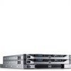
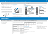
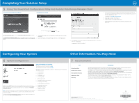
Setting Up Your PowerVault Network Attached Storage Solution 1 | Racking Your Solution WARNING: Before you set up and operate your Dell PowerVault system, review the safety instructions that came with your system. Read The Dell Software License Agreement • Before using your system, please read the Dell Software License Agreement that came with the system. • If you do not accept the terms of the agreement, please call the customer assistance telephone number. For customers in the United States, call 800-WWW-DELL (800-999-3355). For customers outside the United States, visit support.dell.com and select your country or region from the top of the page. Install The Solution In A Rack • The solution requires a properly grounded electrical outlet, a compatible rack, and a rack installation kit. • For information about installing the rails for the PowerVault NX3500 system, see the Rack Installation Instructions that shipped with your rail kit. • For information about installing rails for the backup power supply, see the Dell PowerVault NX3500 Getting Started Guide. Verify Package Contents Verify that all components listed on your packing slip are available. Save all documentation and accessories. Locate Your System Service Tag • Your system is identified by a unique Express Service Code and Service Tag number. The Express Service Code and Service Tag are found on the front of the system by pulling out the information tag. • This information is used by Dell to route support calls to the appropriate personnel. Installation Guidelines • The PowerVault NX3500 hardware configuration consists of two PowerVault NX3500 controller units and one backup power supply (BPS) unit. The BPS is required even if you have an uninterruptible power supply system in your environment. Install the three hardware components adjacent to one another in the same rack. • You must use twelve Category 5E or Category 6 Ethernet cables with RJ45 connectors. • It is recommended that you use a minimum of four network switches. 2 | Cabling Your Solution Planning Proper planning is essential to successfully deploy the PowerVault NX3500 solution. This placemat contains one scenario using two redundant iSCSI networks. If your SAN is configured in a different configuration, see the Administrator's Guide for additional cabling options. It is recommended that you complete the IP chart in step 4 prior to deploying the solution. The IP chart is also present in the Administrator's Guide. Network Cabling Power Cabling SAN Switches Client Switches PowerVault NX3500 Controller 0 PowerVault NX3500 Contoller 0 PowerVault NX3500 Contoller 1 PowerVault storage array MD32x0i/MD36x0i Client connections Internal Network and SAN connections Peer Connections USB Power To power source 1 PowerVault NX3500 Controller 1 USB To power source 2 Power Backup Power Supply To power source 1 PowerVault NX3500 controller 0 PowerVault NX3500 controller 1 To the grid To power source 2 Before You Begin 3 | Turning On The Solution Verify that your network environment and modular disk storage arrays are powered on. Turn on the components in the following order: 1. Dell backup power supply 2. Dell PowerVault NX3500 controllers 4 | Preparing Your Environment For The PowerVault NX3500 Solution IP Chart The IP chart helps you plan your configuration. Recording the IP addresses of your solution in a single location enables you to configure your setup faster and more efficiently. Storage Array Identification One of the storage array's iSCSI IPs Maximum MTU size supported by SAN NAS Controller Discovery Controller 0 MAC address Controller 1 MAC address NAS Cluster Identification NAS cluster name Primary Network Configuration NAS management VIP Client access VIP Controller 0 IP Controller 1 IP Subnet mask Gateway NAS Appliance Setup Worksheet Internal Network Configuration SAN Network Configuration Internal IP a 0 SANa IP controller 0 Internal IP a 1 SANa IP controller 1 Internal IP a 2 SANb IP controller 0 Internal IP a 3 SANb IP controller 1 Subnet mask Internal IP b 0 Internal IP b 1 Internal IP b 2 Internal IP b 3 Subnet mask Configuration Results NAS controller 0 IQN NAS controller 1 IQN Configuration Results NAS controller 0 IQN NAS controller 1 IQN Notes Use the IQNs recorded from the PowerVault Configuration Utility to complete your mappings configuration on the MD. The MAC address for the controller is located on the information tag. Use the embedded NIC 1 MAC address. Management Station Setup Management station IP (IPv4) Verify PVCU software is installed Enable JavaScript on the default browser Verify IPv6 is enabled Environment Setup DNS server IP Your Infrastructure SMTP IP NTP server IP SNMP IP Active directory IP LDAP/NIS IP Terms Used In The IP Chart Controller- A server appliance installed with the Dell scalable file system software. An essential component of a PowerVault NAS clustered solution. Internal IP- IP address used for internal operations between the NAS controllers and the storage subsystem. SAN network/iSCSI network- The network that carries the block level (iSCSI) traffic and to which the storage subsystem is connected. It is recommended that this network be separated from the client network. NAS cluster name-The name that is used to identify the PowerVault NX3500 solution. NAS management VIP-IP addresses that the management stations use to access the PowerVault NX3500 controllers. Client access VIP- IP address that clients use to access CIFS shares and NFS exports hosted by a PowerVault NAS solution. The PowerVault NAS solution supports multiple client access VIPs. Preparing The Management Station • Connect the management station to the client switch. • Verify that IPv6 is enabled. • Install the PowerVault Configuration Utility software. • Download SSH client for CLI access. Preparing The Modular Disk Storage Arrays 1. Create a disk group for each virtual disk. 2. Create a virtual disk in each disk group. Virtual disks must be created and assigned to the host group in pairs. A minimum of 2 virtual disks is required and a maximum of sixteen is supported. 3. Create a host group. For example, name host group PV-NX3500. 4. Map the virtual disks to the host group. 5. Note: Additional configuration is required after completing the steps in the PowerVault Configuration Utility. For more information see step 5.
-
 1
1 -
 2
2
 |
 |