Dell R710 Hardware Manual
Dell R710 - PowerEdge - 4 GB RAM Manual
 |
UPC - 884116025849
View all Dell R710 manuals
Add to My Manuals
Save this manual to your list of manuals |
Dell R710 manual content summary:
- Dell R710 | Hardware Manual - Page 1
Dell™ PowerEdge™ R710 Systems Hardware Owner's Manual - Dell R710 | Hardware Manual - Page 2
A CAUTION indicates potential damage to hardware or loss of data if instructions are not followed. WARNING: A Dell, the DELL logo, and PowerEdge are trademarks of Dell Inc.; Intel is a registered trademark of Intel Corporation in the U.S. and other countries; Microsoft, Windows, and Windows Server - Dell R710 | Hardware Manual - Page 3
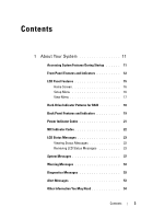
Your System 11 Accessing System Features During Startup 11 Front-Panel Features and Indicators 12 LCD Panel Features 15 Home Screen 16 Setup Menu 16 View Menu 17 Hard-Drive Indicator Patterns for RAID 18 Back Panel Features and Indicators 19 Power Indicator Codes 21 NIC Indicator Codes 22 - Dell R710 | Hardware Manual - Page 4
56 System Setup Options 57 Main Screen 57 Memory Settings Screen 59 Processor Settings Screen 60 SATA Settings Screen 60 Boot Settings Screen 61 Integrated Devices Screen 62 PCI IRQ Assignments Screen 63 Serial Communication Screen 63 Embedded Server Management Screen 64 Power Management - Dell R710 | Hardware Manual - Page 5
/SATA Hard-Drive Configurations . . . 81 Removing a Hard-Drive Blank 81 Installing a Hard-Drive Blank 82 Removing a Hot-Swap Hard Drive 82 Installing a Hot-Swap Hard Drive 83 Removing a Hard Drive From a Hard-Drive Carrier 84 Installing a Hard Drive Into a Hard-Drive Carrier 84 Power Supplies - Dell R710 | Hardware Manual - Page 6
Cable 93 Installing the Internal USB Cable 93 Integrated Dell Remote Access Controller 6 (iDRAC6) Enterprise Card (Optional 94 Installing an iDRAC6 Enterprise Card 94 Removing an iDRAC6 Enterprise Card 95 VFlash Media (Optional 96 NIC Hardware Key 97 Cooling Shroud 98 Removing the Cooling - Dell R710 | Hardware Manual - Page 7
1 124 Removing Expansion-Card Riser 2 125 Replacing Expansion-Card Riser 2 126 Removing Expansion-Card Riser 2 From the Expansion-Card Bracket 127 Replacing the Riser 2 Board on the Expansion-Card Bracket 128 System Memory 129 General Memory Module Installation Guidelines 129 Mode-Specific - Dell R710 | Hardware Manual - Page 8
Memory Modules 136 Processors 137 Removing a Processor 137 Installing a Processor 140 System Battery 141 Replacing the System Battery 141 Control Panel Assembly 143 Removing the Control Panel Display Module . . . 143 Installing the Control Panel Display Module . . . . 143 Removing the Control - Dell R710 | Hardware Manual - Page 9
the System Battery 158 Troubleshooting Power Supplies 158 Troubleshooting System Cooling Problems 159 Troubleshooting a Fan 160 Troubleshooting System Memory 160 Troubleshooting an Internal SD Card 162 Troubleshooting an Internal USB Memory Key . . . . . 163 Troubleshooting an Optical Drive - Dell R710 | Hardware Manual - Page 10
175 Selecting Devices for Testing 175 Selecting Diagnostics Options 175 Viewing Information and Results 176 6 Jumpers and Connectors 177 System Board Jumpers 177 System Board Connectors 180 SAS Backplane Board Connectors 182 Expansion-Card Riser-Board Components and PCIe Buses 185 Disabling - Dell R710 | Hardware Manual - Page 11
Enters the System Setup program. See "Using the System Setup Program and UEFI Boot Manager." Enters System Services, which opens the Unified Server Configurator from which you can access utilities such as system diagnostics. See the Unified Server Configurator user documentation for - Dell R710 | Hardware Manual - Page 12
Front-Panel Features and Indicators Figure 1-1. Front-Panel Features and Indicators (2.5-Inch Chassis) 1 2 3 45 67 8 9 10 11 Figure 1-2. Front-Panel Features and Indicators (3.5-Inch Chassis) 1 2 3 45 67 8 9 10 12 About Your System - Dell R710 | Hardware Manual - Page 13
information including the Express Service tag, Embedded NIC1 MAC address, and iDRAC6 Enterprise card MAC address. The power-on indicator lights when the system power is on. The power button controls the DC power supply output to the system. When the system bezel is installed, the power button is not - Dell R710 | Hardware Manual - Page 14
9 Optical drive (optional) 10 Hard drives 11 Flex bay Description Allows you to navigate the control panel LCD menu. Provides system ID, status information, and system error messages. The LCD lights blue during normal system operation. The LCD lights amber when the system needs attention - Dell R710 | Hardware Manual - Page 15
specific status codes. The LCD backlight lights blue during normal operating conditions and lights amber to indicate an error condition. When the system is iDRAC utility, the LCD panel, or other tools. Figure 1-3. LCD Panel Features 1 23 4 Item Buttons 1 Left 2 Select 3 Right 4 System - Dell R710 | Hardware Manual - Page 16
following tables for information on the Setup and View submenus. Setup Menu NOTE: When selecting an option in the Setup menu, you are asked to confirm the option before you can continue. Option DRAC Set error Set home Description Select DHCP or Static IP to configure the network mode. If Static IP - Dell R710 | Hardware Manual - Page 17
for DRAC, iSCSIn, or NETn. Displays the name of the Host, Model, or User String for the system. Displays the Asset tag or the Service tag for the system. Displays the power output of the system in BTU/hr or Watts. The display format can be configured in the "Set home" submenu of the Setup menu - Dell R710 | Hardware Manual - Page 18
Only) Blinks green two times per second Off Condition Identify drive/preparing for removal Drive ready for insertion or removal NOTE: The drive status indicator remains off until all hard drives are initialized after system power is applied. Drives are not ready for insertion or removal during this - Dell R710 | Hardware Manual - Page 19
off Blinks amber four times per second Blinks green slowly Steady green Condition Drive predicted failure Drive failed Drive rebuilding Drive online Back Panel Features and Indicators Figure 1-5. Back Panel Features 1 2 , 24.13-cm [9.5-in]) (no slot 4 with this option) About Your System 19 - Dell R710 | Hardware Manual - Page 20
4 PCIe slot 4 5 power supply 1 (PS1) 6 power supply 2 (PS2) 7 system identification button 8 system status indicator 9 system status indicator connector 10 Ethernet connectors (4) 11 USB connectors (2) 12 video connector 13 serial connector 14 iDRAC6 Enterprise port (optional) 15 - Dell R710 | Hardware Manual - Page 21
installed power supply. CAUTION: When correcting a power supply mismatch, replace only the power supply with the flashing indicator. Swapping the opposite power supply to make a matched pair can result in an error condition and unexpected system shutdown. To change from a High Output configuration - Dell R710 | Hardware Manual - Page 22
Figure 1-6. Power Supply Status Indicator 1 1 power supply status NIC Indicator Codes Figure 1-7. NIC Indicators 1 2 1 link indicator 2 activity indicator Indicator Link and activity indicators are off Description The NIC is not connected to the network. 22 About Your System - Dell R710 | Hardware Manual - Page 23
For information on the SEL and configuring system management settings, see the systems management software documentation. NOTE: If your system fails to boot, press the System ID button for at least five seconds until an error code appears on the LCD. Record the code, then see "Getting Help." Viewing - Dell R710 | Hardware Manual - Page 24
1-1. LCD Status Messages Code Text E1000 Failsafe voltage error. Contact support. E1114 Ambient Temp exceeds allowed range. E1116 Memory disabled, temp above range. Power cycle AC. E1210 Motherboard battery failure. Check battery. E1211 RAID Controller battery failure. Check battery. E1216 3.3V - Dell R710 | Hardware Manual - Page 25
has failed. Failed. Reseat DIMMs. Reseat the memory modules. See "Troubleshooting System Memory." E122E On-board regulator failed. Call support. One of the on-board voltage regulators failed. Remove AC power to the system for 10 seconds and restart the system. If the problem persists - Dell R710 | Hardware Manual - Page 26
would put the "Troubleshooting a Fan." system at risk of over- heating. E1410 System Fatal A fatal system error has Error been detected. detected. Check LCD for additional scrolling messages. Remove AC power to the system for 10 seconds and restart the system. If the problem persists, see - Dell R710 | Hardware Manual - Page 27
E1422 CPU # machine check error. Power cycle AC. The system BIOS has reported a machine check error. Remove AC power to the system for 10 seconds and restart the system. If the problem persists, see "Getting Help." E1610 Power Supply # (### W) missing. Check power supply. Specified power supply - Dell R710 | Hardware Manual - Page 28
configuration requires more power than the power supplies can provide, even with throttling. Turn off power to the system, reduce the hardware configuration or install higher-wattage power supplies, and then restart the system. E1710 I/O channel check error. Review & clear SEL. The system BIOS - Dell R710 | Hardware Manual - Page 29
the reported a PCI system error PCIe expansion cards. If on a component that the problem persists, see resides in PCI "Troubleshooting configuration space at bus Expansion Cards." ##, device ##, function ##. PCI system error on Slot #. Review & clear SEL. The system BIOS has Reinstall the - Dell R710 | Hardware Manual - Page 30
the SEL for more information, and then clear the SEL. Remove AC power to the system for 10 seconds, and restart the system. If the problem persists, see "Getting Help." E1717 CPU # internal error. Review & clear SEL. The system BIOS has determined that the specified processor has had an internal - Dell R710 | Hardware Manual - Page 31
hard drive fault. Review has experienced a fault. & clear SEL. See "Troubleshooting a Hard Drive." E1812 Hard drive ## The specified hard drive Information only. removed. has been removed from the Check drive. system. E1A11 PCI Riser PCIe risers are not hardware & configured correctly - Dell R710 | Hardware Manual - Page 32
detected during memory Check DIMMs. configuration. See "Troubleshooting System Memory." E2012 Memory configured but unusable. Check DIMMs. Memory configured, but is unusable. See "Troubleshooting System Memory." E2013 BIOS unable to shadow memory. Check DIMMs. The system BIOS failed to copy - Dell R710 | Hardware Manual - Page 33
(continued) Code Text Cause Corrective Actions E2014 CMOS RAM failure. Power cycle AC. CMOS failure. CMOS RAM not functioning properly. Remove AC power to the system for 10 seconds and restart the system. If the problem persists, see "Getting Help." E2015 DMA Controller failure. Power cycle - Dell R710 | Hardware Manual - Page 34
power to the system for 10 seconds and restart the system. If the problem persists, see "Getting Help." E201E POST memory BIOS POST memory test test failure. failure. Check DIMMs. See "Troubleshooting System Memory." If the problem persists, see "Getting Help." E2020 CPU Processor configuration - Dell R710 | Hardware Manual - Page 35
memory configuration. E2110 Multibit Error on DIMM ##. Reseat DIMM. The memory module in slot See "Troubleshooting "##" has had a multi-bit System Memory." error (MBE). E2111 SBE log disabled on DIMM ##. Reseat DIMM. The system BIOS has Remove AC power to the disabled memory single-bit system - Dell R710 | Hardware Manual - Page 36
. If problem persists, replace the RAID battery. See "Installing a RAID Battery." W1627 Power required > PSU wattage. Check PSU and config. The system configuration requires more power than what the power supply can provide. Turn off power to the system, reduce the hardware configuration or - Dell R710 | Hardware Manual - Page 37
in a configuration that supports Advanced ECC Memory Mode. Check other system messages for additional information for possible causes. For memory configuration information, see "General Memory Module Installation Guidelines." If the problem persists, see "Troubleshooting System Memory." About Your - Dell R710 | Hardware Manual - Page 38
a configuration that supports node interleaving. Check other system messages for additional information for possible causes. For memory configuration information, see "General Memory Module Installation Guidelines." If the problem persists, see "Troubleshooting System Memory." 38 About Your System - Dell R710 | Hardware Manual - Page 39
current configuration does not support redundant memory. A memory module may be faulty. Check the memory modules for failure. See "Troubleshooting System Memory." Reset the memory setting, if appropriate. See "Using the System Setup Program and UEFI Boot Manager." Alert! System fatal error during - Dell R710 | Hardware Manual - Page 40
BIOS settings. See "Using the System Setup Program and UEFI Boot Manager." CPU set to minimum frequency. The processor speed may be If not an intentional setting, intentionally set lower for check any other system power conservation. messages for possible causes. CPU x installed with no memory - Dell R710 | Hardware Manual - Page 41
the System Setup Program and UEFI Boot Manager." Decreasing Faulty or improperly Reseat the memory modules. available memory installed memory modules. See "Troubleshooting System Memory." DIMM configuration on each CPU should match. Invalid memory configuration on a dualprocessor system. The - Dell R710 | Hardware Manual - Page 42
appropriate action to resolve the problem. Invalid configuration information please run SETUP program. An invalid system configuration caused a system halt. Run the System Setup program and review the current settings. See "Using the System Setup Program and UEFI Boot Manager." Invalid PCIe card - Dell R710 | Hardware Manual - Page 43
address, read value expecting value Faulty or improperly See "Troubleshooting System installed memory modules. Memory." Memory Initialization Warning: Memory size may be reduced Invalid memory configuration. The system will run but with less memory than is physically available. Ensure that the - Dell R710 | Hardware Manual - Page 44
See "Troubleshooting System installed memory modules. Memory." Memory set to minimum frequency. The memory frequency may If not an intentional setting, be intentionally set lower for check any other system power conservation. messages for possible causes. The current memory configuration may - Dell R710 | Hardware Manual - Page 45
Use a bootable USB key, CD, or hard drive. If the problem persists, see "Troubleshooting an Internal SD Card," "Troubleshooting a USB Device," "Troubleshooting an Optical Drive," and "Troubleshooting a Hard Drive." See "Using the System Setup Program and UEFI Boot Manager" for information on setting - Dell R710 | Hardware Manual - Page 46
in socket. Invalid memory configuration. Ensure that the memory modules are installed in a valid configuration. See "General Memory Module Installation Guidelines." Read fault Requested sector not found The operating system cannot Replace the optical medium, read from the hard drive, USB medium - Dell R710 | Hardware Manual - Page 47
port x device configuration error SATA port x device error Sector not found Faulty hard drive, USB Seek error device, or USB medium. Seek operation failed Replace the USB medium or device. Ensure that the USB or SAS backplane cables are properly connected. See "Troubleshooting a USB Device - Dell R710 | Hardware Manual - Page 48
See "Troubleshooting the System Battery." Time-of-day not Incorrect Time or Date set - please run settings; faulty system SETUP program battery. Check the Time and Date settings. See "Using the System Setup Program and UEFI Boot Manager." If the problem persists, replace the system battery. See - Dell R710 | Hardware Manual - Page 49
) Message Causes Corrective Actions Timer chip Faulty system board. counter 2 failed See "Getting Help." TPM configuration operation honored. System will now reset. A TPM configuration Information only. command has been entered. The system will reboot and execute the command. TPM - Dell R710 | Hardware Manual - Page 50
support.dell.com. See the iDRAC6 user's guide for instructions on performing a field replacement of the flash memory. Unexpected interrupt in protected mode Improperly seated memory modules or faulty keyboard/mouse controller chip. Reseat the memory modules. See "Troubleshooting System Memory - Dell R710 | Hardware Manual - Page 51
when in mirror or BIOS setup screen. See 128-bit advanced "System Memory." ECC modes: x,x,x Warning: A fatal A fatal system error occurred Check the SEL for error has caused and caused the system to information that was logged system reset! reboot. during the error. See the Please check - Dell R710 | Hardware Manual - Page 52
be supported configuration. If the system system by the power supplies. boots without this warning, configuration. then the replaced Warning! Performance degraded. CPU and memory set to minimum frequencies to meet PSU wattage. System will component(s) are not supported with this power supply - Dell R710 | Hardware Manual - Page 53
an Internal SD Card," and "Troubleshooting a Hard Drive." NOTE: For the full name of an abbreviation or acronym used in this table, see "Glossary." Warning Messages A warning message alerts you to a possible problem and prompts you to respond before the system continues a task. For example - Dell R710 | Hardware Manual - Page 54
and tools for configuring and managing your system, including those pertaining to the operating system, system management software, system updates, and system components that you purchased with your system. NOTE: Always check for updates on support.dell.com and read the updates first because they - Dell R710 | Hardware Manual - Page 55
the system hardware configuration • Enable or disable integrated devices • Set performance and power management thresholds • Manage system security Choosing the System Boot Mode The System Setup program also enables you to specify the boot mode for installing your operating system: • BIOS boot mode - Dell R710 | Hardware Manual - Page 56
of the message and suggestions for correcting errors. NOTE: After installing a memory upgrade, it is normal for your system to display a message that the system memory size has changed the first time you start your system. Using the System Setup Program Navigation Keys Keys Action Up arrow - Dell R710 | Hardware Manual - Page 57
Main System Setup Program Screen NOTE: The options for the System Setup program change based on the system configuration. NOTE: The System Setup program defaults are listed under their respective options in the following sections, where applicable. Option System Time System Date Memory Settings - Dell R710 | Hardware Manual - Page 58
Embedded Server Management Power Management System Security Keyboard NumLock (On default) Report Keyboard Errors (Report default) Description Displays a screen to enable or disable the integrated SATA controller and ports. See "SATA Settings Screen." Displays a screen to specify the boot mode (BIOS - Dell R710 | Hardware Manual - Page 59
see "System Memory." Node Interleaving (Disabled default) If this field is Enabled, memory interleaving is supported if a symmetric memory configuration is installed. If Disabled, the system supports Non-Uniform Memory architecture (NUMA) (asymmetric) memory configurations. Using the System Setup - Dell R710 | Hardware Manual - Page 60
Embedded SATA (ATA Mode default) Port A (Auto default) Description ATA Mode enables the integrated SATA controller. Off disables the controller. Auto enables BIOS support for the device attached to SATA port A. Off disables BIOS support for the device. 60 Using the System Setup Program and UEFI - Dell R710 | Hardware Manual - Page 61
SD card slot. A device installed in the internal SD card slot will automatically emulate a hard drive. If you install a device in this slot that is configured as a removable diskette drive, you must manually set the emulation type to Floppy. Using the System Setup Program and UEFI Boot Manager 61 - Dell R710 | Hardware Manual - Page 62
allows the system to boot from the network. MAC Address Displays the MAC address for the NIC. Capability Detected Displays the features of the NIC hardware key, if installed. NOTE: Some NIC features may require the installation of an additional driver. 62 Using the System Setup Program and - Dell R710 | Hardware Manual - Page 63
is usable only with operating systems that support WDAT implementations of the Advanced Configuration and Power Interface (ACPI) 3.0b specification. Enables or disables the I/O Acceleration Technology feature. Enables or disables BIOS support for the integrated video controller. NOTE: This field can - Dell R710 | Hardware Manual - Page 64
, or None through another LCD configuration utility (such as the iDRAC Configuration Utility or the LCD panel menu). User-Defined LCD String You can enter a name or other identifier for the system, to be displayed on the LCD module screen. 64 Using the System Setup Program and UEFI Boot Manager - Dell R710 | Hardware Manual - Page 65
Custom setting, the BIOS pre-configures the power settings on this screen as follows: • OS Control sets the CPU power to OS DBPM, the fan power to Minimum Power, and the memory power to Maximum Performance. In this setting, all processor performance information is passed from the system BIOS to the - Dell R710 | Hardware Manual - Page 66
unchanged (all user settings for the TPM are preserved). NOTE: This field is read-only when TPM Security is set to Off. 66 Using the System Setup Program and UEFI Boot Manager - Dell R710 | Hardware Manual - Page 67
do so by qualified support personnel or by the operating system's documentation. Pressing this button halts the operating system and displays a diagnostic screen. Enables or disables the NMI feature. AC Power Recovery (Last default) Determines how the system reacts when power is restored. If set - Dell R710 | Hardware Manual - Page 68
, Microsoft® Windows Server® 2008 x64 version) to be installed from the UEFI boot mode. DOS and 32-bit operating systems can only be installed from the BIOS boot mode. NOTE: The Boot Mode must be set to UEFI in the System Setup program to access the UEFI Boot Manager. The UEFI Boot Manager enables - Dell R710 | Hardware Manual - Page 69
order; or execute a one-time boot option. Enables you to access the System Setup program, System Services, and BIOS-level boot options. UEFI Boot Settings Screen Option Add Boot Option Delete Boot Option Enable/Disable Boot Option Change Boot Order One-Time Boot From File Description Adds a new - Dell R710 | Hardware Manual - Page 70
Option System Services BIOS Boot Manager Reboot System Description Restarts the system and accesses the Unified Server Configurator, which enables you to run utilities such as system diagnostics. Accesses the BIOS-level boot options list without rebooting. This option enables you to conveniently - Dell R710 | Hardware Manual - Page 71
or the left-arrow key. NOTE: To escape from the field without assigning a system password, press to move to another field, or press prior . System Password changes to Enabled. Exit the System Setup program and begin using your system. 6 Either reboot the system now for the - Dell R710 | Hardware Manual - Page 72
be shut down manually with the power button. Even after you shut down and restart the system, the error message continues to be displayed until the correct password is entered. NOTE: You can use the Password Status option in conjunction with the System Password and Setup Password options to protect - Dell R710 | Hardware Manual - Page 73
iDRAC6 and for the managed server. The iDRAC Configuration Utility enables you to: • Configure, enable, or disable the iDRAC6 local area network through the dedicated iDRAC6 Enterprise card port or the embedded NICs. • Enable or disable IPMI over LAN. Using the System Setup Program and UEFI Boot - Dell R710 | Hardware Manual - Page 74
the documentation for iDRAC6 and systems management applications. Entering the iDRAC Configuration Utility 1 Turn on or restart your system. 2 Press when prompted during POST. If your operating system begins to load before you press , allow the system to finish booting, and then - Dell R710 | Hardware Manual - Page 75
only perform troubleshooting and simple repairs as authorized in your product documentation, or as directed by the online or telephone service and support team. Damage due to servicing that is not authorized by Dell is not covered by your warranty. Read and follow the safety instructions that came - Dell R710 | Hardware Manual - Page 76
backplane 13 RAID battery (PERC only) 15 control panel 2 Internal SD Module 4 memory modules (up to 18 total, 9 for each processor) 6 power supply bays (2) 8 riser 1 (PCIe slots 1 and 2) 10 integrated storage controller card 12 SAS or SATA hard drives (up to 8) 14 flex bay for optional tape backup - Dell R710 | Hardware Manual - Page 77
Bezel (Optional) A lock on the bezel restricts access to the power button, optical drive, and hard drive(s). The LCD panel and navigation buttons are accessible through the front bezel. See Figure 3-2. Removing the Front Bezel 1 Using the system key, unlock the bezel. 2 Pull up on the release latch - Dell R710 | Hardware Manual - Page 78
slide-out label panel for system information including the Express Service tag, Embedded NIC1 MAC address, and iDRAC6 Enterprise card MAC address. Removing release the bottom portion of the tag. 5 Remove the tag. Replacing the Information Tag 1 Remove the front bezel. See "Removing the Front Bezel." - Dell R710 | Hardware Manual - Page 79
only perform troubleshooting and simple repairs as authorized in your product documentation, or as directed by the online or telephone service and support team. Damage due to servicing that is not authorized by Dell is not covered by your warranty. Read and follow the safety instructions that came - Dell R710 | Hardware Manual - Page 80
and backplane, your system has one of the following configurations: • Eight 2.5-inch drive bays • Four 3.5-inch drive bays with a flex bay for the optional tape backup unit • Six 3.5-inch drive bays without the flex bay All chassis support hot-swappable SAS and SATA hard drives, and the 2.5inch - Dell R710 | Hardware Manual - Page 81
are supplied in special hotswappable hard-drive carriers that fit in the hard-drive bays. CAUTION: Before attempting to remove or install a drive while the system is running, see the documentation for the storage controller card to ensure that the host adapter is configured correctly to support hot - Dell R710 | Hardware Manual - Page 82
2 2.5-in hard drive blank Installing a Hard-Drive Blank Align the hard-drive blank with the drive bay and insert the blank into the drive bay until the release lever clicks into place. Removing a Hot-Swap Hard Drive CAUTION: Ensure that your operating system supports hot-swap drive removal and - Dell R710 | Hardware Manual - Page 83
ensure that your operating system supports hotswap drive installation. See the documentation supplied with your operating system. 1 If present, remove the front bezel. See "Removing the Front Bezel." 2 If a drive blank is present in the bay, remove it. See "Removing a Hard- Drive Blank." Installing - Dell R710 | Hardware Manual - Page 84
the hard-drive carrier into the drive bay until the carrier contacts the backplane. c Close the handle to lock the drive in place. 4 If applicable, install the bezel. See "Installing the Front Bezel." Removing a Hard Drive From a Hard-Drive Carrier Remove the screws from the slide rails on the hard - Dell R710 | Hardware Manual - Page 85
3 Attach the four screws to secure the hard drive to the hard-drive carrier. Figure 3-6. Installing a Hard Drive into a Drive Carrier 3 2 1 4 1 hard-drive carrier 3 hard drive 2 screws (4) 4 SAS screw hole Installing System Components 85 - Dell R710 | Hardware Manual - Page 86
the PS1 power supply bay. CAUTION: To ensure proper system cooling, the power supply blank must be installed in the PS2 bay in a non-redundant configuration. See "Installing the Power Supply Blank." Removing a Power Supply CAUTION: If troubleshooting a power supply mismatch error, replace only the - Dell R710 | Hardware Manual - Page 87
Figure 3-7. Removing and Installing a Power Supply 1 2 3 1 power supply handle 3 release latch 2 Velcro strap Replacing a Power Supply 1 On a system with redundant power supplies, verify that both power supplies are the same type and have the same maximum output power. NOTE: The maximum output - Dell R710 | Hardware Manual - Page 88
: To ensure proper system cooling, the power supply blank must be installed in the second power supply bay in a non-redundant configuration. Remove the power supply blank only if you are installing a second power supply. Installing the Power Supply Blank NOTE: Install the power supply blank only in - Dell R710 | Hardware Manual - Page 89
connector) 6 internal SD module cable 8 control panel board 4 Connect the internal SD module cable to the connector on the control panel board. See Figure 3-8. 5 Close the system. See "Closing the System." 6 Reconnect the system and peripherals to their power sources, and turn them on. Installing - Dell R710 | Hardware Manual - Page 90
authorized by Dell is not covered by your warranty. Read and follow the safety instructions that came with the product. NOTE: To use an SD card with your system, ensure that the internal SD card port is enabled in the System Setup program. See "Using the System Setup Program and UEFI Boot Manager - Dell R710 | Hardware Manual - Page 91
screen of the System Setup program. See "Using the System Setup Program and UEFI Boot Manager." To boot from the USB memory key, configure the USB memory key with a boot image and then specify the USB memory key in the boot sequence in the System Setup program. Installing System Components 91 - Dell R710 | Hardware Manual - Page 92
that is not authorized by Dell is not covered by your warranty. Read and follow the safety instructions that came with the product. NOTE: Maximum dimensions supported for the USB memory key are 24-mm (.94-in) wide, 79-mm (3.11-in) long, and 8.6-mm (.33-in) tall. 1 Turn off the system, including any - Dell R710 | Hardware Manual - Page 93
only perform troubleshooting and simple repairs as authorized in your product documentation, or as directed by the online or telephone service and support team. Damage due to servicing that is not authorized by Dell is not covered by your warranty. Read and follow the safety instructions that came - Dell R710 | Hardware Manual - Page 94
Reconnect the system and peripherals to their power sources, and turn them on. Integrated Dell Remote Access Controller 6 (iDRAC6) Enterprise Card (Optional) The optional iDRAC6 Enterprise card provides a set of advanced features for managing the server remotely. Installing an iDRAC6 Enterprise Card - Dell R710 | Hardware Manual - Page 95
only perform troubleshooting and simple repairs as authorized in your product documentation, or as directed by the online or telephone service and support team. Damage due to servicing that is not authorized by Dell is not covered by your warranty. Read and follow the safety instructions that came - Dell R710 | Hardware Manual - Page 96
system. See "Closing the System." 10 Reconnect the system and peripherals to their power sources, and turn them on. VFlash Media (Optional) The optional VFlash media is a Secure Digital (SD) card that can be used with the optional iDRAC6 Enterprise card. See "Integrated Dell Remote Access Controller - Dell R710 | Hardware Manual - Page 97
is not authorized by Dell is not covered by your warranty. Read and follow the safety instructions that came with the product. NOTE: When future NIC functionality is supported, you must replace the original NIC hardware key (if installed) with a new hardware key. 1 Turn off the system, including any - Dell R710 | Hardware Manual - Page 98
or telephone service and support team. Damage due to servicing that is not authorized by Dell is not covered by your warranty. Read and follow the safety instructions that came with the product. WARNING: The memory modules are hot to the touch for some time after the system has been powered down - Dell R710 | Hardware Manual - Page 99
develop quickly resulting in a shutdown of the system and the loss of data. Removing the Cooling Shroud 1 Turn off the system, including any attached peripherals, and disconnect the system from the electrical outlet. 2 Open the system. See "Opening the System." 3 Use the lift handles on the cooling - Dell R710 | Hardware Manual - Page 100
telephone service and support team. Damage due to servicing that is not authorized by Dell is not covered by your warranty. Read and follow the safety instructions that came with the product. CAUTION: The cooling fans are hot-swappable. To maintain proper cooling while the system is on, replace only - Dell R710 | Hardware Manual - Page 101
the fan straight up from the fan bracket. See Figure 3-13. Figure 3-13. Removing and Installing a Cooling Fan 2 1 3 1 fan 3 fan bracket 2 fan release handle Replacing a Cooling Fan 1 Align the fan plug with the connector at the base of the fan bracket and lower the fan into the bracket until the - Dell R710 | Hardware Manual - Page 102
only perform troubleshooting and simple repairs as authorized in your product documentation, or as directed by the online or telephone service and support team. Damage due to servicing that is not authorized by Dell is not covered by your warranty. Read and follow the safety instructions that came - Dell R710 | Hardware Manual - Page 103
the fans in the fan bracket. See "Replacing a Cooling Fan." 4 Close the system. See "Closing the System." Optical Drive An optional slimline DVD-ROM or DVD+RW optical drive slides into the front panel and connects to the SATA controller on the system board. The optical drive is on the right or left - Dell R710 | Hardware Manual - Page 104
only perform troubleshooting and simple repairs as authorized in your product documentation, or as directed by the online or telephone service and support team. Damage due to servicing that is not authorized by Dell is not covered by your warranty. Read and follow the safety instructions that came - Dell R710 | Hardware Manual - Page 105
8 Close the system. See "Closing the System." 9 Replace the bezel. See "Installing the Front Bezel." 10 Reconnect your system and peripherals to their electrical outlets, and turn on the system. Figure 3-15. Removing and Installing the Optical Drive 2 3 1 4 1 optical drive 3 power cable 2 optical - Dell R710 | Hardware Manual - Page 106
Figure 3-16. Routing the Optical Drive Cable (2.5-inch Hard-Drive Chassis) 1 2 1 optical drive connector 3 SATA_A connector 4 3 2 DVD/TBU_PWR connector 4 cable retention bracket 106 Installing System Components - Dell R710 | Hardware Manual - Page 107
either to the SATA controller on the system board for a SATA device, or to the SCSI controller expansion card for a SCSI device. Installing the Tape Backup Unit CAUTION: Many repairs may only be done by a certified service technician. You should only perform troubleshooting and simple repairs as - Dell R710 | Hardware Manual - Page 108
disassemble the blank tray: • For 2.5-inch hard-drive systems, remove the slide rails from the tray. • For 3.5-inch hard-drive systems, remove the blank from the tray. See Figure 3-18. 5 For a SCSI tape drive, route the SCSI data and power cables through the flex bay and through the tray and connect - Dell R710 | Hardware Manual - Page 109
1 4 1 drive blank 3 tray 2 screws (4) 4 tape backup unit 6 Install the slide rails or tray on controller expansion card in one of the expansion-card slots. See "Installing an Expansion Card." 9 Connect the power cable to the power connector on the back of the tape backup unit. Installing System - Dell R710 | Hardware Manual - Page 110
only perform troubleshooting and simple repairs as authorized in your product documentation, or as directed by the online or telephone service and support team. Damage due to servicing that is not authorized by Dell is not covered by your warranty. Read and follow the safety instructions that came - Dell R710 | Hardware Manual - Page 111
card slot on riser 1 for an integrated storage controller card that provides the storage subsystem for your system's internal hard drives. The controller supports SAS and SATA hard drives and also enables you to set up the hard drives in RAID configurations as supported by the version of the storage - Dell R710 | Hardware Manual - Page 112
only perform troubleshooting and simple repairs as authorized in your product documentation, or as directed by the online or telephone service and support team. Damage due to servicing that is not authorized by Dell is not covered by your warranty. Read and follow the safety instructions that came - Dell R710 | Hardware Manual - Page 113
to the controller's SAS_1 connector. NOTE: Be sure to connect the cable according to the connector labels on the cable. The cables are not operational if reversed. 5 For a battery-cached PERC controller, install the RAID battery. See "Installing a RAID Battery." Installing System Components 113 - Dell R710 | Hardware Manual - Page 114
on the backplane. 8 Close the system. See "Closing the System." 9 Reconnect your system and peripherals to their electrical outlets, and turn on the system. Figure 3-21. Storage Controller Card Cabling (2.5-in Hard-Drive Chassis) 1 2 3 45 6 78 1 RAID battery (PERC only) 3 SAS A connector on - Dell R710 | Hardware Manual - Page 115
in Hard-Drive Chassis) 1 2 3 45 6 78 1 RAID battery (PERC only) 3 SAS A connector on backplane 5 integrated storage controller card 7 SAS_1 connector 2 SAS B connector on backplane 4 cable retention bracket 6 SAS_0 connector 8 RAID battery connector (PERC only) Installing System Components - Dell R710 | Hardware Manual - Page 116
section applies only to systems with the optional PERC controller card. Removing a RAID Battery 1 Pull back gently on the right edge of the battery bay and draw out the RAID battery from the battery carrier. 2 Disconnect the cable between the RAID battery and the storage controller card. See Figure - Dell R710 | Hardware Manual - Page 117
Installing a RAID Battery 1 Connect the battery cable to the connector on the battery. 2 Locate the battery bay on top of the hard drive bays. See Figure 3-1. 3 With the cable oriented toward the back, angle the left side of the RAID battery into the left side of the battery bay. See Figure 3-24. 4 - Dell R710 | Hardware Manual - Page 118
back are routed along a cable path within the interior right wall of the system chassis. The cables are secured by a cable retention bracket that attaches to 1 cable retention bracket 3 hooks (3) 5 chassis slots (6) 2 release latch 4 right chassis wall 6 tab (3) 118 Installing System Components - Dell R710 | Hardware Manual - Page 119
back until the latch engages. 2 Install the cooling fan bracket. See "Replacing the Fan Bracket." 3 Install the cooling shroud. See "Installing the Cooling Shroud." Expansion Cards and Expansion-Card Risers The system supports up to four PCI Express (PCIe) expansion cards on two expansion-card - Dell R710 | Hardware Manual - Page 120
hot-swappable. • Besides the integrated storage controller, the system supports a maximum of two PERC or SAS controller expansion cards to manage external storage. CAUTION: To ensure proper cooling no more than two of the four expansion cards can have a power consumption of greater than 15W (up to - Dell R710 | Hardware Manual - Page 121
it for installation. For instructions, see the documentation accompanying the card. 2 Turn off the system, including any attached peripherals, and disconnect the system from the electrical outlet. 3 Open the system. See "Opening the System." 4 Open the expansion-card guide latch and remove the - Dell R710 | Hardware Manual - Page 122
troubleshooting and simple repairs as authorized in your product documentation, or as directed by the online or telephone service and support team. Damage due to servicing that is not authorized by Dell is not covered by your warranty. Read and follow the safety instructions of the system chassis. - Dell R710 | Hardware Manual - Page 123
only perform troubleshooting and simple repairs as authorized in your product documentation, or as directed by the online or telephone service and support team. Damage due to servicing that is not authorized by Dell is not covered by your warranty. Read and follow the safety instructions that came - Dell R710 | Hardware Manual - Page 124
of the riser to release the board from the card slot and lift expansion-card riser 1 off of the mounting pins and out of the system. See Figure 3-27. Replacing Expansion-Card Riser 1 NOTE: The system will not start with a riser board removed. 1 Aligning the pin collar over the mounting pin on the - Dell R710 | Hardware Manual - Page 125
only perform troubleshooting and simple repairs as authorized in your product documentation, or as directed by the online or telephone service and support team. Damage due to servicing that is not authorized by Dell is not covered by your warranty. Read and follow the safety instructions that came - Dell R710 | Hardware Manual - Page 126
2 and lift the riser straight up to clear the chassis. See Figure 3-28. Replacing Expansion-Card Riser 2 1 Align the guides on each end of expansion-card riser 2 with the mounting pins on the system board, and lower the riser into the system until the latches on the riser the engage. See Figure 3-28 - Dell R710 | Hardware Manual - Page 127
Figure 3-28. Removing and Replacing Expansion-Card Riser 2 2 3 1 4 5 1 expansion-card riser 2 3 pin collars (2) 5 riser 2 connector on system board 2 release latch 4 mounting pins (2) Removing Expansion-Card Riser 2 From the Expansion-Card Bracket 1 Turn off the system and attached peripherals, - Dell R710 | Hardware Manual - Page 128
riser board off of the four securing tab hooks. c Lift the riser board from the bracket. Replacing the Riser 2 Board on the Expansion-Card Bracket 1 Place the riser board in the expansion-card bracket Phillips screwdriver, secure the board with the Phillips screw. 128 Installing System Components - Dell R710 | Hardware Manual - Page 129
GB and 2-GB UDIMMs are supported for a total of up to 24 GB. General Memory Module Installation Guidelines To ensure optimal performance of your system, observe the following general guidelines when configuring your system memory. NOTE: Memory configurations that fail to observe these guidelines can - Dell R710 | Hardware Manual - Page 130
x8 DRAM device widths. • The memory speed of each channel depends on the memory configuration: - For single or dual-rank memory modules: • One memory module per channel supports up to 1333 MHz. • Two memory modules per channel supports up to 1067 MHz. • Three memory modules per channel are limited - Dell R710 | Hardware Manual - Page 131
Support The system supports memory mirroring if identical memory modules are installed in the two channels closest to the processor (memory is not installed in the farthest channel). Mirroring must be enabled in the System Setup program. In a mirrored configuration, the total available system memory - Dell R710 | Hardware Manual - Page 132
Rank Memory Configurations (Per Processor) Memory Mode Memory Sockets Single Processor Dual Processor Memory 1 2 3 Physical Available Physical Available Module Size 4 7 5 8 6 Memory Memory Memory Memory 48 72 all 16 all 32 48 32 64 96 96 144 132 Installing System Components - Dell R710 | Hardware Manual - Page 133
Memory Configurations (Per Processor) Memory Mode Memory Sockets Single Processor Dual Processor Memory 1 2 3 Physical Available Physical Available Module Size 4 7 5 8 6 Memory Memory Memory Memory 1 When available 2 Requires x4- or x8-based memory modules Installing System Components 133 - Dell R710 | Hardware Manual - Page 134
or telephone service and support team. Damage due to servicing that is not authorized by Dell is not covered by your warranty. Read and follow the safety instructions that came with the product. WARNING: The memory modules are hot to the touch for some time after the system has been powered down - Dell R710 | Hardware Manual - Page 135
from the electrical outlet. 2 Open the system. See "Opening the System." 3 Remove the cooling shroud. See "Removing the Cooling Shroud." 4 Locate the memory module sockets. See Figure 6-2. 5 Press outward on the memory module ejectors to allow the memory module to be inserted into the socket. See - Dell R710 | Hardware Manual - Page 136
or telephone service and support team. Damage due to servicing that is not authorized by Dell is not covered by your warranty. Read and follow the safety instructions that came with the product. WARNING: The memory modules are hot to the touch for some time after the system has been powered down - Dell R710 | Hardware Manual - Page 137
or telephone service and support team. Damage due to servicing that is not authorized by Dell is not covered by your warranty. Read and follow the safety instructions that came with the product. 1 Prior to upgrading your system, download the latest system BIOS version from support.dell.com and - Dell R710 | Hardware Manual - Page 138
aside upside down (thermal grease side facing up). Figure 3-31. Installing and Removing the Heat Sink 2 1 1 heat sink 2 release lever (2) CAUTION: The processor is held in its socket under strong the processor shield upward and out of the way. See Figure 3-32. 138 Installing System Components - Dell R710 | Hardware Manual - Page 139
the socket is ready for the new processor. If you are permanently removing the processor, you must install a processor blank and a heat-sink blank in the CPU2 socket to ensure proper system cooling. Adding the blanks is similar to installing a processor. See "Installing a Processor." Installing - Dell R710 | Hardware Manual - Page 140
as directed by the online or telephone service and support team. Damage due to servicing that is not authorized by Dell is not covered by your warranty. Read and follow the safety instructions that came with the product. NOTE: In a single-processor configuration, the CPU1 socket must be used. 1 If - Dell R710 | Hardware Manual - Page 141
. System Battery Replacing the System Battery CAUTION: Many repairs may only be done by a certified service technician. You should only perform troubleshooting and simple repairs as authorized in your product documentation, or as directed by the online or telephone service and support team - Dell R710 | Hardware Manual - Page 142
tabs at the negative side of the connector. Figure 3-33. Replacing the System Battery 1 2 3 1 positive side of battery connector 3 negative side of battery connector 2 system battery 6 Install the new system battery. a Support the battery connector by pressing down firmly on the positive side of - Dell R710 | Hardware Manual - Page 143
only perform troubleshooting and simple repairs as authorized in your product documentation, or as directed by the online or telephone service and support team. Damage due to servicing that is not authorized by Dell is not covered by your warranty. Read and follow the safety instructions that came - Dell R710 | Hardware Manual - Page 144
Removing the Control Panel Board CAUTION: Many repairs may only be done by a certified service technician. You should only perform troubleshooting and simple repairs as authorized in your product documentation, or as directed by the online or telephone service and 144 Installing System Components - Dell R710 | Hardware Manual - Page 145
support team. Damage due to servicing that is not authorized by Dell is not covered by your warranty. Read and follow the safety instructions that came with the product. 1 Turn off the system and attached peripherals, and disconnect the system from the electrical outlet and peripherals. 2 Open the - Dell R710 | Hardware Manual - Page 146
only perform troubleshooting and simple repairs as authorized in your product documentation, or as directed by the online or telephone service and support team. Damage due to servicing that is not authorized by Dell is not covered by your warranty. Read and follow the safety instructions that came - Dell R710 | Hardware Manual - Page 147
Figure 3-35. Removing and Installing a SAS Backplane 3 4 5 2 1 6 7 8 1 drive bays 3 power cable from system board 5 SAS B cable 7 securing tabs (7) 2 SAS backplane board 4 SAS A cable 6 securing slots (8) 8 SAS backplane board release tab Installing a SAS Backplane 1 Install the SAS - Dell R710 | Hardware Manual - Page 148
, you must supply the recovery key for your data before you can access the encrypted data on your hard drives. See the documentation for your encryption software for more information. NOTE: After replacing the system board, you are required to update the Unified Server Configurator repository to the - Dell R710 | Hardware Manual - Page 149
SAS drives from the system before removing the backplane. CAUTION: You must note the number of each hard drive and temporarily label them before removal to ensure that you can replace them in the same locations. a Remove all hard drives. See "Removing a Hot-Swap Hard Drive." b Disconnect the power - Dell R710 | Hardware Manual - Page 150
labels from the placard and affix them to the information tag on the front of the system. See Figure 1-1. 3 Transfer the processors and heat sinks to the new system board. See "Removing a Processor." 4 Remove the memory modules and transfer them to the same locations on the new board. See "Removing - Dell R710 | Hardware Manual - Page 151
9 If applicable, reconnect the RAID battery cable to the storage controller card. 10 Reconnect all power and interface cables (see Figure 6-2 for the locations of the connectors on the system board). 11 If removed, reinstall the SAS backplane and all hard drives. See "System Board." 12 Install all - Dell R710 | Hardware Manual - Page 152
152 Installing System Components - Dell R710 | Hardware Manual - Page 153
by the online or telephone service and support team. Damage due to servicing that is not authorized by Dell is not covered by your warranty. Read and follow the safety instructions that came with the product. Troubleshooting System Startup Failure If your system halts during startup prior to - Dell R710 | Hardware Manual - Page 154
appropriate online diagnostic test. See "Using Dell™ PowerEdge™ Diagnostics." If the tests run successfully, the problem is not related to video hardware. If the tests fail, see "Getting Help." Troubleshooting a USB Device 1 Use the following steps to troubleshoot a USB keyboard and/or mouse. For - Dell R710 | Hardware Manual - Page 155
is resolved, replace the serial device. If the problem persists, see "Getting Help." Troubleshooting a NIC 1 Run the appropriate online diagnostic test. See "Using Dell™ PowerEdge™ Diagnostics." 2 Restart the system and check for any system messages pertaining to the NIC controller. 3 Check the - Dell R710 | Hardware Manual - Page 156
from the system. See "Installing System Components." • Cooling shroud • Hard drives • SD cards • USB memory key • NIC hardware key • Internal SD Module • Expansion cards and both expansion-card risers • Integrated storage controller • iDRAC6 Enterprise card 156 Troubleshooting Your System - Dell R710 | Hardware Manual - Page 157
test. See "Using Dell™ PowerEdge™ Diagnostics." If the tests fail, see "Getting Help." Troubleshooting a Damaged System CAUTION: Many repairs may only be done by a certified service technician. You should only perform troubleshooting and simple repairs as authorized in your product documentation - Dell R710 | Hardware Manual - Page 158
telephone service and support team. Damage due to servicing that is not authorized by Dell is not covered by your warranty. Read and follow the safety instructions that came with the product. If the problem is not resolved by replacing the battery, see "Getting Help." Troubleshooting Power Supplies - Dell R710 | Hardware Manual - Page 159
that is not authorized by Dell is not covered by your warranty. Read and follow the safety instructions that came with the product. Ensure that none of the following conditions exist: • System cover, cooling shroud, drive blank, power supply blank (in single power supply configurations), or front or - Dell R710 | Hardware Manual - Page 160
authorized in your product documentation, or as directed by the online or telephone service and support team. Damage due to servicing that is not authorized by Dell is not covered by your warranty. Read and follow the safety instructions that came with the product. 160 Troubleshooting Your System - Dell R710 | Hardware Manual - Page 161
Module Installation Guidelines" and verify that your memory configuration complies with all applicable guidelines. 1 If the system is operational, run the appropriate online diagnostic test. See "Using Dell™ PowerEdge™ Diagnostics." If diagnostics indicates a fault, follow the corrective actions - Dell R710 | Hardware Manual - Page 162
, or as directed by the online or telephone service and support team. Damage due to servicing that is not authorized by Dell is not covered by your warranty. Read and follow the safety instructions that came with the product. 1 Enter the System Setup program and ensure that the internal SD card port - Dell R710 | Hardware Manual - Page 163
, or as directed by the online or telephone service and support team. Damage due to servicing that is not authorized by Dell is not covered by your warranty. Read and follow the safety instructions that came with the product. 1 Enter the System Setup program and ensure that the internal USB key port - Dell R710 | Hardware Manual - Page 164
the device drivers for the optical drive are installed and are configured correctly 4 Enter the System Setup program and ensure that the drive's controller is enabled. See "Using the System Setup Program and UEFI Boot Manager." 5 Run the appropriate online diagnostic test. See "Using Dell™ PowerEdge - Dell R710 | Hardware Manual - Page 165
and support team. Damage due to servicing that is not authorized by Dell is not covered by your warranty. Read and follow the safety instructions that came with the product. 1 Try using a different tape cartridge. 2 Ensure that the device drivers for the tape drive are installed and are configured - Dell R710 | Hardware Manual - Page 166
the online or telephone service and support team. Damage due to servicing that is not authorized by Dell is not covered by your warranty. Read and follow the safety instructions that came with the product. CAUTION: This troubleshooting procedure can destroy data stored on the hard drive. Before you - Dell R710 | Hardware Manual - Page 167
system, enter the System Setup program, and verify that the controller is enabled and the drives appear in the System Setup program. See "Using the System Setup Program and UEFI Boot Manager." If the problem persists, see "Troubleshooting a Storage Controller." Troubleshooting a Storage Controller - Dell R710 | Hardware Manual - Page 168
or telephone service and support team. Damage due to servicing that is not authorized by Dell is not covered by your warranty. Read and follow the safety instructions that came with the product. NOTE: When troubleshooting an expansion card, see the documentation for your operating system and the - Dell R710 | Hardware Manual - Page 169
, and disconnect the system from the electrical outlet. b Open the system. See "Opening the System." c Reinstall one of the expansion cards. d Close the system. See "Closing the System." e Run the appropriate diagnostic test. If the tests fail, see "Getting Help." Troubleshooting Your System 169 - Dell R710 | Hardware Manual - Page 170
service and support team. Damage due to servicing that is not authorized by Dell is not covered by your warranty. Read and follow the safety instructions that came with the product. 1 Run the appropriate online diagnostics test. See "Using Dell™ PowerEdge™ Diagnostics." 2 Turn off the system - Dell R710 | Hardware Manual - Page 171
Replace the processor with the processor you removed in step 13. See "Installing a Processor." 22 Replace the cooling shroud. See "Installing the Cooling Shroud." 23 Repeat step 15 through step 17. If the problem persists, the system board is faulty. See "Getting Help." Troubleshooting Your System - Dell R710 | Hardware Manual - Page 172
172 Troubleshooting Your System - Dell R710 | Hardware Manual - Page 173
problem. Using Dell™ PowerEdge™ Diagnostics To assess a system problem, first use the online Dell PowerEdge Diagnostics. Dell PowerEdge Diagnostics is a suite of diagnostic programs, or test modules, that include diagnostic tests on chassis and storage components such as hard drives, physical memory - Dell R710 | Hardware Manual - Page 174
may cause invalid results or error messages. 1 As the system boots, press . 2 Select Diagnostics from the System Services menu. 3 Select Launch Diagnostics. 4 From the Diagnostics main menu, select Run Diags, or select MpMemory if you are troubleshooting memory. The Diagnostics menu allows you - Dell R710 | Hardware Manual - Page 175
the tests to continue without user intervention in the event that one of the tests has failed. • Log output file pathname - Enables you to specify the diskette drive or USB memory key where the test log file is saved. You cannot save the file to a hard drive. Running the System Diagnostics 175 - Dell R710 | Hardware Manual - Page 176
Displays the test that ran and the result. • Errors - Displays any errors that occurred during the test. • Help - Displays information about the currently selected device, component, or test. • Configuration - Displays basic configuration information about the currently selected device. • Parameters - Dell R710 | Hardware Manual - Page 177
only perform troubleshooting and simple repairs as authorized in your product documentation, or as directed by the online or telephone service and support team. Damage due to servicing that is not authorized by Dell is not covered by your warranty. Read and follow the safety instructions that came - Dell R710 | Hardware Manual - Page 178
PWRD_EN Pins 2 and 4 The password feature is enabled. (default) Pins 4 and 6 The password feature is disabled and iDRAC6 local access is unlocked at the next AC power cycle. NVRAM_CLR Pins 3 and 5 The configuration settings are retained at (default) system boot. 178 Jumpers and Connectors - Dell R710 | Hardware Manual - Page 179
Pins 1 and 3 The configuration settings are cleared at the next system boot. If the configuration settings become corrupted to the point where the system will not boot, install the jumper and boot the system. Remove the jumper before restoring the configuration information. Jumpers and Connectors - Dell R710 | Hardware Manual - Page 180
System Board Connectors Figure 6-2. System Board Connectors 2 1 20 21 22 3 4 5 19 6 18 17 16 15 14 13 12 11 10 9 8 7 Connector 1 RISER2 2 RISER1 Description expansion-card riser 2 connector expansion-card riser 1 connector 180 Jumpers and Connectors - Dell R710 | Hardware Manual - Page 181
lever) memory module slot B6 memory module slot B9 System cooling fan Backplane power connector Processor 2 System cooling fan System battery Power connector for optical drive and tape backup unit System cooling fan Processor 1 Control panel USB interface connector System cooling fan Control panel - Dell R710 | Hardware Manual - Page 182
memory module slot A5 memory module slot A8 memory module slot A3(white release lever) memory module slot A6 memory module slot A9 Power supply connector for PS2 Power supply connector for PS1 NIC hardware key SAS Backplane Board Connectors Figure 6-3. SAS Backplane Board for 2.5-Inch Hard Drives - Dell R710 | Hardware Manual - Page 183
1 drive 0 - drive 3 connectors 3 backplane power (BKPLN) 5 SAS B connector 2 drive 4- drive 7 connectors 4 SAS A connector Figure 6-4. SAS Backplane Board for 3.5-Inch Hard Drives (4 Slots) 1 2 3 4 front 6 5 1 drive 1 connector 3 drive 3 connector 5 backplane power (BP_PWR) back 2 drive 0 - Dell R710 | Hardware Manual - Page 184
6-5. SAS Backplane Board for 3.5-Inch Hard Drives (6 Slots) 1 2 3 4 5 6 front 9 8 7 back 1 drive 1 connector 3 drive 3 connector 5 drive 5 connector 7 backplane power (BP_PWR) 9 SAS B connector 2 drive 0 connector 4 drive 2 connector 6 drive 4 connector 8 SAS A connector 184 Jumpers - Dell R710 | Hardware Manual - Page 185
1 Components 1 2 5 4 3 1 slot 1 PCIe - x4 link (full-height, 30.99- 2 slot 2 PCIe - x4 link (low profile, 24.13- cm [12.2-in] length) cm [9.5-in] length) 3 storage controller socket 4 card edge connector 5 release button Jumpers and Connectors 185 - Dell R710 | Hardware Manual - Page 186
Figure 6-7. Standard PCIe Expansion-Card Riser 2 Components 1 2 3 4 5 6 1 chassis intrusion switch 3 slot 3 PCIe x8 link (full-height, 24.13- cm [9.5-in] length) 5 pin collars (2) 2 screw 4 slot 4 PCIe x8 link (full-height, 24.13- cm [9.5-in] length) 6 card edge connector 186 Jumpers and - Dell R710 | Hardware Manual - Page 187
only perform troubleshooting and simple repairs as authorized in your product documentation, or as directed by the online or telephone service and support team. Damage due to servicing that is not authorized by Dell is not covered by your warranty. Read and follow the safety instructions that came - Dell R710 | Hardware Manual - Page 188
and peripherals to their electrical outlets, and turn on the system. The existing passwords are not disabled (erased) until the system boots with the password jumper plug in the disabled position. However, before you assign a new system and/or setup password, you must reset the jumper plug to the - Dell R710 | Hardware Manual - Page 189
, or Dell product catalog. Dell provides several online and telephone-based support and service options. Availability varies by country and product, and some services may not be available in your area. To contact Dell for sales, technical support, or customer service issues: 1 Visit support.dell.com - Dell R710 | Hardware Manual - Page 190
190 Getting Help - Dell R710 | Hardware Manual - Page 191
A module that contains a processor, memory, and a hard drive. The modules are mounted into a chassis that includes power supplies and fans. bootable media - A diskette, USB memory key, or optical media that is used to start your system in lieu of the hard drives. BTU - British thermal unit. bus - An - Dell R710 | Hardware Manual - Page 192
access memory. A system's RAM is usually made up entirely of DRAM chips. driver - See device driver. DVD - Digital versatile disc or digital video disc. ECC - Error checking and correction. EMI - Electromagnetic interference. ESD - Electrostatic discharge. ESM - Embedded server management. See iDRAC - Dell R710 | Hardware Manual - Page 193
memory However, when referring to hard-drive capacity, the term is iDRAC, iDRAC6 - Integrated Dell Remote Access Controller. A systems management hardware and software solution that provides remote management capabilities, crashed system recovery, and power control functions for Dell PowerEdge systems - Dell R710 | Hardware Manual - Page 194
, when referring to hard-drive capacity, the term is often rounded to mean 1,000,000 bytes. Mbps - Megabits per second. MBps - Megabytes per second. MBR - Master boot record. memory address - A specific location, usually expressed as a hexadecimal number, in the system's RAM. memory module - A small - Dell R710 | Hardware Manual - Page 195
system configuration information. parity - Redundant information that is associated with a block of data. parity stripe - In RAID arrays, the parity-striped hard drive of a set of striped hard drives contains parity data that enable data recovery in the event that one of the other hard drives fails - Dell R710 | Hardware Manual - Page 196
one processor must usually be revised to run on another processor. CPU is a synonym for processor. PSU - Power supply unit. PXE - Preboot eXecution Environment. A way of booting a system via a LAN (without a hard drive or bootable diskette). QPI- QuickPath Interconnect. The bus interface between the - Dell R710 | Hardware Manual - Page 197
a modem to the system. service tag - A bar code label on the system used to identify it when you call Dell for technical support. SMART - Self-Monitoring Analysis and Reporting Technology. Allows hard drives to report errors and failures to the system BIOS and then display an error message on the - Dell R710 | Hardware Manual - Page 198
DDR3 memory module. UEFI - Unified Extensible Firmware Interface. uplink port - A port on a network hub or switch used to connect to other hubs or switches without requiring a crossover cable. UPS - Uninterruptible power supply. A battery-powered unit that automatically supplies power to your system - Dell R710 | Hardware Manual - Page 199
graphics resolution, you must install the appropriate video drivers and your monitor must support the resolution. virtualization - The ability via software to share the resources of a single computer across multiple environments. A single physical system may appear to the user as multiple virtual - Dell R710 | Hardware Manual - Page 200
200 Glossary - Dell R710 | Hardware Manual - Page 201
Index A Advanced ECC memory mode, 131 B back panel features, 19 backplane See SAS backplane. battery (RAID) installing, 116 removing, 116 battery (system) replacing, 141 troubleshooting, 158 BIOS boot mode, 55 blank hard drive, 81 power supply, 88 boot mode, 55 C cable retention bracket installing, - Dell R710 | Hardware Manual - Page 202
, 79 D damaged systems troubleshooting, 157 Dell contacting, 189 diagnostics testing options, 174 using Dell PowerEdge Diagnostics, 173 DIMMs See memory modules (DIMMs). drive blank installing, 82 removing, 81 drive carrier hard drive, 84 DVD drive See optical drive. E error messages, 56 expansion - Dell R710 | Hardware Manual - Page 203
, 82 troubleshooting, 166 heat sink, 138 hot-swap cooling fans, 100 hard drives, 80 power supplies, 86 I iDRAC Configuration Utility, 73 iDRAC6 Enterprise card installing, 94 removing, 95 indicators back panel, 19 front-panel, 12 NIC, 22 power, 12, 21 information tag removing, 78 replacing, 78 - Dell R710 | Hardware Manual - Page 204
132 removing, 136 UDIMM configurations, 120, 134 204 Index messages error messages, 56 status LCD, 23 system, 37 warning, 53 microprocessor See processor. N NIC hardware key, 97 NICs connectors, 20 hardware key, 97 indicators, 22 troubleshooting, 155 O optical drive installing, 104 removing, 104 - Dell R710 | Hardware Manual - Page 205
drive blank, 81 hard drive from a drive carrier, 84 hard drives, 82 iDRAC6 Enterprise card, 95 information tag, 78 integrated storage controller, 112 internal SD flash card, 90 internal SD module, 90 internal USB cable, 93 memory modules, 136 optical drive, 104 PCIe expansion cards, 122 power supply - Dell R710 | Hardware Manual - Page 206
setup password, 72 SSD hard drives, 80 startup accessing system features, 11 storage controller cabling for 2.5-in HDD chassis, 114 cabling for four 3.5-in HDD chassis, 115 cabling for six 3.5-in HDD chassis, 116 installing, 112 removing, 112 troubleshooting, 167 support contacting Dell, 189 system - Dell R710 | Hardware Manual - Page 207
, 66 troubleshooting cooling fans, 160 damaged system, 157 external connections, 153 hard drive, 166 internal USB memory key, 163 keyboard, 154 memory, 160 NIC, 155 optical drive, 164 PCIe expansion cards, 168 power supplies, 158 processor(s), 170 SD card, 162 storage controller, 167 system battery - Dell R710 | Hardware Manual - Page 208
208 Index
-
 1
1 -
 2
2 -
 3
3 -
 4
4 -
 5
5 -
 6
6 -
 7
7 -
8
-
9
-
10
-
11
-
12
-
13
-
14
-
15
-
16
-
17
-
18
-
19
-
20
-
21
-
22
-
23
-
24
-
25
-
26
-
27
-
28
-
29
-
30
-
31
-
32
-
33
-
34
-
35
-
36
-
37
-
38
-
39
-
40
-
41
-
42
-
43
-
44
-
45
-
46
-
47
-
48
-
49
-
50
-
51
-
52
-
53
-
54
-
55
-
56
-
57
-
58
-
59
-
60
-
61
-
62
-
63
-
64
-
65
-
66
-
67
-
68
-
69
-
70
-
71
-
72
-
73
-
74
-
75
-
76
-
77
-
78
-
79
-
80
-
81
-
82
-
83
-
84
-
85
-
86
-
87
-
88
-
89
-
90
-
91
-
92
-
93
-
94
-
95
-
96
-
97
-
98
-
99
-
100
-
101
-
102
-
103
-
104
-
105
-
106
-
107
-
108
-
109
-
110
-
111
-
112
-
113
-
114
-
115
-
116
-
117
-
118
-
119
-
120
-
121
-
122
-
123
-
124
-
125
-
126
-
127
-
128
-
129
-
130
-
131
-
132
-
133
-
134
-
135
-
136
-
137
-
138
-
139
-
140
-
141
-
142
-
143
-
144
-
145
-
146
-
147
-
148
-
149
-
150
-
151
-
152
-
153
-
154
-
155
-
156
-
157
-
158
-
159
-
160
-
161
-
162
-
163
-
164
-
165
-
166
-
167
-
168
-
169
-
170
-
171
-
172
-
173
-
174
-
175
-
176
-
177
-
178
-
179
-
180
-
181
-
182
-
183
-
184
-
185
-
186
-
187
-
188
-
189
-
190
-
191
-
192
-
193
-
194
-
195
-
196
-
197
-
198
-
199
-
200
-
201
-
202
-
203
-
204
-
205
-
206
-
207
-
208
 |
 |

Dell™ PowerEdge™
R710 Systems
Hardware Owner’s Manual