| Section |
Page |
| Dell™ PowerEdge™ R710 Systems Hardware Owner’s Manual |
1 |
| Notes, Cautions, and Warnings |
2 |
| Contents |
3 |
| 1 |
11 |
| About Your System |
11 |
| Accessing System Features During Startup |
11 |
| Front-Panel Features and Indicators |
12 |
| Figure 1-1. Front-Panel Features and Indicators (2.5-Inch Chassis) |
12 |
| Figure 1-2. Front-Panel Features and Indicators (3.5-Inch Chassis) |
12 |
| LCD Panel Features |
15 |
| Figure 1-3. LCD Panel Features |
15 |
| Home Screen |
16 |
| Setup Menu |
16 |
| View Menu |
17 |
| Hard-Drive Indicator Patterns for RAID |
18 |
| Figure 1-4. Hard-Drive Indicators |
18 |
| Back Panel Features and Indicators |
19 |
| Figure 1-5. Back Panel Features |
19 |
| Power Indicator Codes |
21 |
| Figure 1-6. Power Supply Status Indicator |
22 |
| NIC Indicator Codes |
22 |
| Figure 1-7. NIC Indicators |
22 |
| LCD Status Messages |
23 |
| Viewing Status Messages |
23 |
| Removing LCD Status Messages |
23 |
| Table 1-1. LCD Status Messages |
24 |
| System Messages |
37 |
| Table 1-2. System Messages |
37 |
| Warning Messages |
53 |
| Diagnostics Messages |
53 |
| Alert Messages |
53 |
| Other Information You May Need |
54 |
| 2 |
55 |
| Using the System Setup Program and UEFI Boot Manager |
55 |
| Choosing the System Boot Mode |
55 |
| Entering the System Setup Program |
56 |
| 1 Turn on or restart your system. |
56 |
| 2 Press <F2> after you see the following message: |
56 |
| Responding to Error Messages |
56 |
| Using the System Setup Program Navigation Keys |
56 |
| System Setup Options |
57 |
| Main Screen |
57 |
| Figure 2-1. Main System Setup Program Screen |
57 |
| Memory Settings Screen |
59 |
| Processor Settings Screen |
60 |
| SATA Settings Screen |
60 |
| Boot Settings Screen |
61 |
| Integrated Devices Screen |
62 |
| PCI IRQ Assignments Screen |
63 |
| Serial Communication Screen |
63 |
| Embedded Server Management Screen |
64 |
| Power Management Screen |
65 |
| System Security Screen |
66 |
| Exit Screen |
67 |
| Entering the UEFI Boot Manager |
68 |
| 1 Turn on or restart your system. |
68 |
| 2 Press <F11> after you see the following message: |
68 |
| Using the UEFI Boot Manager Navigation Keys |
68 |
| UEFI Boot Manager Screen |
69 |
| UEFI Boot Settings Screen |
69 |
| System Utilities Screen |
69 |
| System and Setup Password Features |
70 |
| Using the System Password |
70 |
| Assigning a System Password |
70 |
| 1 Verify that Password Status is Unlocked. |
70 |
| 2 Highlight the System Password option and press <Enter>. |
71 |
| 3 Type your new system password. |
71 |
| 4 Press <Enter>. |
71 |
| 5 To confirm your password, type it a second time and press <Enter>. |
71 |
| 6 Either reboot the system now for the password protection to take effect or continue working. |
71 |
| Using Your System Password to Secure Your System |
71 |
| 1 Turn on or reboot your system by pressing <Ctrl><Alt><Del>. |
71 |
| 2 Type your password and press <Enter>. |
71 |
| 1 Turn on or reboot your system by pressing <Ctrl><Alt><Del>. |
71 |
| 2 Type your password and press <Ctrl><Enter>. |
71 |
| Changing an Existing System Password |
72 |
| 1 Enter the System Setup program by pressing <F2> during POST. |
72 |
| 2 Select the System Security screen. |
72 |
| 3 Verify that the Password Status is Unlocked. |
72 |
| 4 Type the new system password in the two password fields. |
72 |
| Disabling the System Password |
72 |
| Using the Setup Password |
72 |
| Assigning a Setup Password |
72 |
| Operating With a Setup Password Enabled |
73 |
| Deleting or Changing an Existing Setup Password |
73 |
| 1 Enter the System Setup program and select the System Security. |
73 |
| 2 Highlight Setup Password, press <Enter> to access the setup password window. Press <Enter> twice to clear the existing setup password. |
73 |
| 3 If you want to assign a new setup password, perform the steps in \ |
73 |
| iDRAC Configuration Utility |
73 |
| Entering the iDRAC Configuration Utility |
74 |
| 1 Turn on or restart your system. |
74 |
| 2 Press <Ctrl><E> when prompted during POST. |
74 |
| 3 |
75 |
| Installing System Components |
75 |
| Recommended Tools |
75 |
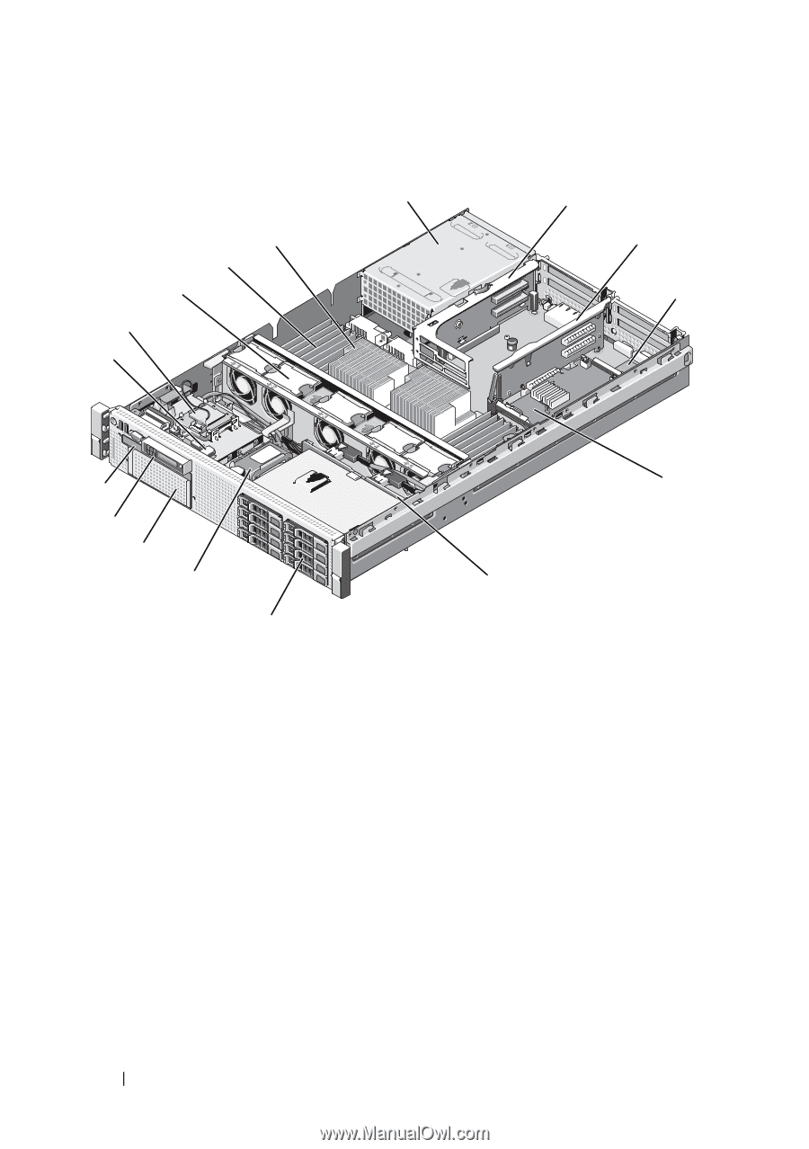
| Inside the System |
75 |
| Figure 3-1. Inside the System (2.5-Inch Hard-Drive Chassis) |
76 |
| Front Bezel (Optional) |
77 |
| Removing the Front Bezel |
77 |
| 1 Using the system key, unlock the bezel. |
77 |
| 2 Pull up on the release latch next to the key lock. |
77 |
| 3 Rotate the left end of the bezel away from the system to release the right end of the bezel. |
77 |
| 4 Pull the bezel away from the system. See Figure 3-2. |
77 |
| Figure 3-2. Removing the Front Bezel |
77 |
| Installing the Front Bezel |
78 |
| 1 Insert the hinge tab on the right of the bezel into the slot on the right side of the system front panel. |
78 |
| 2 Rotate the left side of the bezel toward the system. |
78 |
| 3 Press the bezel to the system to engage the latch. |
78 |
| Information Tag |
78 |
| Removing the Information Tag |
78 |
| 1 Remove the front bezel. See \ |
78 |
| 2 Pull the information tag out of its slot in the chassis until it is in the locked position. See Figure 1-1 and Figure 1-2 in \ |
78 |
| 3 Pull down on the tag until it disengages from the slot in the chassis to release the top portion of the tag. |
78 |
| 4 Pull up on the tag until it disengages from the slot in the chassis to release the bottom portion of the tag. |
78 |
| 5 Remove the tag. |
78 |
| Replacing the Information Tag |
78 |
| 1 Remove the front bezel. See \ |
78 |
| 2 Locate the information tag slot on the front of the system chassis. See Figure 1-1 and Figure 1-2 in \ |
78 |
| 3 Holding the information tag vertically, slide it into the information tag slot until it locks into place. |
78 |
| Opening and Closing the System |
79 |
| Opening the System |
79 |
| 1 Unless you are installing a hot-swappable component such as a cooling fan or power supply, turn off the system and attached peripherals, and disconnect the system from the electrical outlet and peripherals. |
79 |
| 2 Rotate the latch release lock counter-clockwise to the unlocked position. See Figure 3-3. |
79 |
| 3 Lift up on the latch on top of the system and slide the cover back. See Figure 3-3. |
79 |
| 4 Grasp the cover on both sides and lift the cover away from the system. |
79 |
| Closing the System |
79 |
| 1 Lift up the latch on the cover. |
79 |
| 2 Place the cover onto the chassis and offset the cover slightly back so that it clears the chassis hooks and lays flush on the system chassis. See Figure 3-3. |
79 |
| 3 Push down the latch to lever the cover into the closed position. |
79 |
| 4 Rotate the latch release lock in a clockwise direction to secure the cover. |
79 |
| Figure 3-3. Removing or Installing the Cover |
80 |
| Hard Drives |
80 |
| Mixed SAS/SATA Hard-Drive Configurations |
81 |
| Removing a Hard-Drive Blank |
81 |
| 1 Remove the front bezel. See \ |
81 |
| 2 Grasp the front of the hard-drive blank, press the release lever on the right side, and slide the blank out until it is free of the drive bay. See Figure 3-4. |
81 |
| Figure 3-4. Removing and Installing a Hard Drive Blank |
82 |
| Installing a Hard-Drive Blank |
82 |
| Removing a Hot-Swap Hard Drive |
82 |
| 1 If present, remove the front bezel. See \ |
82 |
| 2 From the RAID management software, prepare the drive for removal. Wait until the hard-drive indicators on the drive carrier si... |
82 |
| 3 Press the button on the front of the drive carrier and open the drive carrier release handle to release the drive. See Figure 3-5. |
83 |
| 4 Slide the hard drive out until it is free of the drive bay. |
83 |
| 5 Insert a drive blank in the vacated drive bay. See \ |
83 |
| 6 If applicable, install the bezel. See \ |
83 |
| Installing a Hot-Swap Hard Drive |
83 |
| 1 If present, remove the front bezel. See \ |
83 |
| 2 If a drive blank is present in the bay, remove it. See \ |
83 |
| Figure 3-5. Installing a Hot-Swap Hard Drive |
84 |
| 3 Install the hot-swap hard drive. |
84 |
| a Press the button on the front of the drive carrier and open the handle. |
84 |
| b Insert the hard-drive carrier into the drive bay until the carrier contacts the backplane. |
84 |
| c Close the handle to lock the drive in place. |
84 |
| 4 If applicable, install the bezel. See \ |
84 |
| Removing a Hard Drive From a Hard-Drive Carrier |
84 |
| Installing a Hard Drive Into a Hard-Drive Carrier |
84 |
| 1 Insert the hard drive into the hard-drive carrier with the connector end of the drive at the back. See Figure 3-6. |
84 |
| 2 Align the screw holes on the hard drive with the back set of holes on the hard drive carrier. |
84 |
| 3 Attach the four screws to secure the hard drive to the hard-drive carrier. |
85 |
| Figure 3-6. Installing a Hard Drive into a Drive Carrier |
85 |
| Power Supplies |
86 |
| Removing a Power Supply |
86 |
| 1 Disconnect the power cable from the power source and the power supply you intend to remove and remove the cables from the Velcro strap. |
86 |
| 2 Press the lever release latch and slide the power supply out of the chassis. See Figure 3-7. |
86 |
| Figure 3-7. Removing and Installing a Power Supply |
87 |
| Replacing a Power Supply |
87 |
| 1 On a system with redundant power supplies, verify that both power supplies are the same type and have the same maximum output power. |
87 |
| 2 Slide the new power supply into the chassis until the power supply is fully seated and the release latch snaps into place. See Figure 3-7. |
87 |
| 3 Connect the power cable to the power supply and plug the cable into a power outlet. |
87 |
| Removing the Power Supply Blank |
88 |
| Installing the Power Supply Blank |
88 |
| Internal SD Module |
88 |
| Installing the Internal SD Module |
88 |
| 1 Turn off the system, including any attached peripherals, and disconnect the system from the electrical outlet. |
88 |
| 2 Open the system. See \ |
88 |
| 3 Position the module so the tabs on the underside of the tray fit into the hooks on the chassis, then lower the opposite edge of the card into place. See Figure 3-8. |
88 |
| Figure 3-8. Removing or Installing the Internal SD Module |
89 |
| 4 Connect the internal SD module cable to the connector on the control panel board. See Figure 3-8. |
89 |
| 5 Close the system. See \ |
89 |
| 6 Reconnect the system and peripherals to their power sources, and turn them on. |
89 |
| Removing the Internal SD Module |
90 |
| 1 Turn off the system, including any attached peripherals, and disconnect the system from the electrical outlet. |
90 |
| 2 Open the system. See \ |
90 |
| 3 Disconnect the cable from the internal SD module and from the control panel board. See Figure 3-8. |
90 |
| 4 Lift upwards on the latch securing the internal SD module to the chassis, then lift the tray out of the chassis. See Figure 3-8. |
90 |
| 5 Close the system. See \ |
90 |
| 6 Reconnect the system and peripherals to their power sources, and turn them on. |
90 |
| Internal SD Flash Card |
90 |
| Installing the Internal SD Flash Card |
90 |
| 1 Turn off the system, including any attached peripherals, and disconnect the system from the electrical outlet. |
90 |
| 2 Open the system. See \ |
90 |
| 3 Locate the SD card connector on the internal SD module and, with the label side facing up, insert the contact-pin end of the card into the slot. See Figure 3-8. |
91 |
| 4 Press the card into the card slot to lock it into place. |
91 |
| 5 Close the system. See \ |
91 |
| 6 Reconnect the system to power and restart the system. |
91 |
| Removing the Internal SD Flash Card |
91 |
| 1 Turn off the system, including any attached peripherals, and disconnect the system from the electrical outlet. |
91 |
| 2 Open the system. See \ |
91 |
| 3 Locate the SD card slot on the internal SD module and press inward on the card to release it from the slot and remove the card. |
91 |
| 4 Close the system. See \ |
91 |
| 5 Reconnect the system to power and restart the system. |
91 |
| Internal USB Memory Key |
91 |
| 1 Turn off the system, including any attached peripherals, and disconnect the system from the electrical outlet. |
92 |
| 2 Open the system. See \ |
92 |
| 3 Locate the USB connector on the control panel. See Figure 3-9. |
92 |
| 4 Insert the USB memory key into the USB connector. See Figure 3-9. |
92 |
| Figure 3-9. Removing or Installing a USB Memory Key |
92 |
| 5 Close the system. See \ |
92 |
| 6 Reconnect the system to power and restart the system. |
92 |
| Internal USB Cable |
93 |
| Removing the Internal USB Cable |
93 |
| 1 Turn off the system, including any attached peripherals, and disconnect the system from the electrical outlet. |
93 |
| 2 Open the system. See \ |
93 |
| 3 Remove the fan bracket. See \ |
93 |
| 4 Remove the USB cable from the connector on the control panel. |
93 |
| 5 Remove the USB cable from the cable routing guides on the inside of the chassis. If necessary remove any other cables from the cable routing guides. |
93 |
| 6 Remove the USB cable from the connector on the system board. |
93 |
| Installing the Internal USB Cable |
93 |
| 1 Turn off the system, including any attached peripherals, and disconnect the system from the electrical outlet. |
93 |
| 2 Open the system. See \ |
93 |
| 3 Remove the fan bracket. See \ |
93 |
| 4 Connect the USB cable to the connector on the control panel. |
93 |
| 5 Route the cable through the cable routing guides on the inside of the chassis. |
93 |
| 6 Connect the USB cable to the connector on the system board. |
93 |
| 7 Replace the fan bracket. See \ |
93 |
| 8 Close the system. See \ |
94 |
| 9 Reconnect the system and peripherals to their power sources, and turn them on. |
94 |
| Integrated Dell Remote Access Controller 6 (iDRAC6) Enterprise Card (Optional) |
94 |
| Installing an iDRAC6 Enterprise Card |
94 |
| 1 Turn off the system, including any attached peripherals, and disconnect the system from the electrical outlet. |
94 |
| 2 Open the system. See \ |
94 |
| 3 Remove the plastic filler plug for the iDRAC6 Enterprise port from the system back panel. See \ |
94 |
| 4 If installed, remove all expansion cards from expansion-card riser 1. See \ |
94 |
| 5 Install the iDRAC6 Enterprise card: |
94 |
| a Angle the card so that the RJ-45 connector fits through the back-panel opening. See Figure 3-10. |
94 |
| b Align the front edge of the card with the two front plastic retention standoffs next to the iDRAC6 connector on the system board. See Figure 6-2 for the location of the connector. |
94 |
| c Press the card down until it is fully seated. See Figure 3-10. |
94 |
| 6 Reinstall all expansion cards in expansion-card riser 1. See \ |
95 |
| 7 Close the system. See \ |
95 |
| 8 Reconnect the system and peripherals to their power sources, and turn them on. |
95 |
| Figure 3-10. Removing and Installing the iDRAC6 Enterprise Card |
95 |
| Removing an iDRAC6 Enterprise Card |
95 |
| 1 Turn off the system, including any attached peripherals, and disconnect the system from the electrical outlet. |
95 |
| 2 Open the system. See \ |
95 |
| 3 If installed, remove all expansion cards from expansion-card riser 1. See \ |
96 |
| 4 Remove the VFlash media card (if installed) from the iDRAC6 Enterprise card. See \ |
96 |
| 5 If present, disconnect the Ethernet cable from the iDRAC6 Enterprise card. |
96 |
| 6 Remove the iDRAC6 Enterprise card: |
96 |
| a Pull back slightly on the two tabs at the front edge of the card and gently lift the front edge of the card off of the retention standoffs. |
96 |
| b As the card releases from the standoffs, the connector under the card disengages from the system board connector. |
96 |
| c Slide the card away from the back of the system until the RJ-45 connector is clear of the back panel, then lift the card out of the system. |
96 |
| 7 Install the plastic filler plug for the vacated RJ-45 Ethernet port in the system back panel. |
96 |
| 8 Reinstall the expansion card(s) in expansion-card riser 1. See \ |
96 |
| 9 Close the system. See \ |
96 |
| 10 Reconnect the system and peripherals to their power sources, and turn them on. |
96 |
| VFlash Media (Optional) |
96 |
| 1 Locate the VFlash media slot on the back of the system and insert the contact-pin end of the SD card (with the label side facing up) into the slot. See \ |
96 |
| 2 Press inward on the card to lock it into the slot. |
96 |
| NIC Hardware Key |
97 |
| 1 Turn off the system, including any attached peripherals, and disconnect the system from the electrical outlet. |
97 |
| 2 Open the system. See \ |
97 |
| 3 Locate the ISCSI_KEY connector on the system board. See Figure 6-2. |
97 |
| 4 Insert the NIC hardware key into the connector onto the board. See Figure 3-11. |
97 |
| Figure 3-11. Removing or Installing a NIC Hardware Key |
98 |
| 5 Close the system. See \ |
98 |
| 6 Reconnect the system to the electrical outlet and turn on the system and attached peripherals. |
98 |
| Cooling Shroud |
98 |
| Removing the Cooling Shroud |
99 |
| 1 Turn off the system, including any attached peripherals, and disconnect the system from the electrical outlet. |
99 |
| 2 Open the system. See \ |
99 |
| 3 Use the lift handles on the cooling shroud to lift the shroud out of the system. See Figure 3-12. |
99 |
| Figure 3-12. Removing and Installing the Cooling Shroud |
99 |
| Installing the Cooling Shroud |
100 |
| 1 Align the tabs on the right side of the cooling shroud with the cutouts in the right chassis wall. |
100 |
| 2 Lower the right end of the shroud into the chassis cutouts and rotate the left end down inside the left chassis wall. |
100 |
| 3 Close the system. See \ |
100 |
| 4 Reconnect the system to the electrical outlet and turn on the system and attached peripherals. |
100 |
| Cooling Fans |
100 |
| Removing a Cooling Fan |
100 |
| 1 Open the system. See \ |
100 |
| 2 Press the release tab while grasping the ends of the fan and lift the fan straight up from the fan bracket. See Figure 3-13. |
101 |
| Figure 3-13. Removing and Installing a Cooling Fan |
101 |
| Replacing a Cooling Fan |
101 |
| 1 Align the fan plug with the connector at the base of the fan bracket and lower the fan into the bracket until the fan is fully seated. See Figure 3-13. |
101 |
| 2 Close the system. See \ |
101 |
| Removing the Fan Bracket |
102 |
| 1 Turn off the system, including any attached peripherals, and disconnect the system from the electrical outlet. |
102 |
| 2 Open the system. See \ |
102 |
| 3 Optional: Remove the fans from the fan bracket. See \ |
102 |
| 4 Lift the release latches on each end of the fan bracket and lift the bracket out of the system. See Figure 3-14. |
102 |
| Figure 3-14. Removing and Installing the Processor Fan Bracket |
103 |
| Replacing the Fan Bracket |
103 |
| 1 Align the fan bracket down onto the bracket base so that the mounting pins fit correctly into the bracket base. See Figure 3-14. |
103 |
| 2 Insert the bracket and engage the release levers to lock it in place. |
103 |
| 3 If removed, replace the fans in the fan bracket. See \ |
103 |
| 4 Close the system. See \ |
103 |
| Optical Drive |
103 |
| Removing the Optical Drive |
104 |
| 1 Turn off the system, including any attached peripherals, and disconnect the system from its electrical outlet. |
104 |
| 2 Open the system. See \ |
104 |
| 3 Disconnect the optical drive cable from the back of the optical drive. |
104 |
| 4 To remove the optical drive, press down on the blue release tab at the back of the optical drive and push the drive out of the system. See Figure 3-15. |
104 |
| Installing the Optical Drive |
104 |
| 1 Turn off the system, including any attached peripherals, and disconnect the system from its electrical outlet. |
104 |
| 2 Open the system. See \ |
104 |
| 3 To remove the optical drive blank, press down on the blue release tab at the back of the blank and push the blank out of the system. |
104 |
| 4 Align the optical drive with its opening in the front panel. See Figure 3-15. |
104 |
| 5 Slide in the optical drive until the latch snaps into place. |
104 |
| 6 Connect the optical drive cable to the back of the drive tray. |
104 |
| 7 If not already done, connect the power and interface cables from the optical drive to the system board connectors. |
105 |
| a Connect the power cable to the DVD/TBU_PWR connector on the front of the system board below the fan bracket. See Figure 6-2 for the location of the connector. |
105 |
| b Route the interface cable along the inside right wall of the chassis. See \ |
105 |
| c Connect the cable to the SATA_A connector on the system board. See Figure 6-2 for the location of the connector. |
105 |
| 8 Close the system. See \ |
105 |
| 9 Replace the bezel. See \ |
105 |
| 10 Reconnect your system and peripherals to their electrical outlets, and turn on the system. |
105 |
| Figure 3-15. Removing and Installing the Optical Drive |
105 |
| Figure 3-16. Routing the Optical Drive Cable (2.5-inch Hard-Drive Chassis) |
106 |
| Figure 3-17. Routing the Optical Drive Cable (3.5-inch Hard-Drive Chassis) |
107 |
| Internal Tape Backup Unit |
107 |
| Installing the Tape Backup Unit |
107 |
| 1 Turn off the system, including any attached peripherals, and disconnect the system from its electrical outlet. |
108 |
| 2 Open the system. See \ |
108 |
| 3 Remove the blank tray from the flex bay by squeezing the blue release tabs at the back of the tray and pushing the tray out of the system. |
108 |
| 4 Using a Phillips screwdriver, disassemble the blank tray: |
108 |
| 5 For a SCSI tape drive, route the SCSI data and power cables through the flex bay and through the tray and connect the cables to the tape backup unit. |
108 |
| Figure 3-18. Preparing the Tape Backup Unit and Tray (3.5-in HDD Chassis Only) |
109 |
| 6 Install the slide rails or tray on the tape backup unit. Figure 3-18 shows the 3.5-inch tray installation. |
109 |
| 7 Align the tape backup unit with the flex bay and slide the unit in until the locking mechanism engages. See Figure 3-19. |
109 |
| 8 If you are installing a SCSI tape backup unit, install the SCSI controller expansion card in one of the expansion-card slots. See \ |
109 |
| 9 Connect the power cable to the power connector on the back of the tape backup unit. |
109 |
| 10 Connect the other end of the power cable to the DVD/TBU_PWR connector on the system board. See Figure 6-2. |
110 |
| 11 Connect the interface cable to the back of the tape backup unit. |
110 |
| 12 Connect the other end of the interface cable to the appropriate controller. |
110 |
| a For a SCSI device, connect to the SCSI controller expansion card. |
110 |
| b For a SATA device, connect to the SATA_B connector on the system board. See Figure 6-2 for the location of the connector. |
110 |
| 13 Route the interface cable along the interior right wall. See \ |
110 |
| 14 Close the system. See \ |
110 |
| 15 Reconnect your system and peripherals to their electrical outlets, and turn on the system. |
110 |
| Removing the Tape Backup Unit |
110 |
| 1 Turn off the system, including any attached peripherals, and disconnect the system from its electrical outlet. |
110 |
| 2 Open the system. See \ |
110 |
| 3 For a SATA tape backup unit, disconnect the power and signal cables from the back of the unit. |
110 |
| 4 Squeeze the blue release tabs at the back of the mounting tray and push the tray out of the system. See Figure 3-19. |
110 |
| 5 Using a Phillips screwdriver, remove the slide rails or the tray from the tape backup unit. |
110 |
| 6 For a SCSI tape backup unit, disconnect the power and signal cables from the back of the unit. |
110 |
| 7 Install the slide rails or the tray to the flex-bay blank. |
110 |
| 8 Insert the assembled blank tray into the flex bay and slide the unit in until the locking mechanism engages. |
111 |
| 9 Close the system. See \ |
111 |
| 10 Reconnect your system and peripherals to their electrical outlets, and turn on the system. |
111 |
| Figure 3-19. Removing and Installing the Tape Backup Unit |
111 |
| Integrated Storage Controller Card |
111 |
| Removing the Integrated Storage Controller Card |
112 |
| 1 Turn off the system, including any attached peripherals, and disconnect the system from the electrical outlet. |
112 |
| 2 Open the system. See \ |
112 |
| 3 Remove all expansion cards from expansion-card riser 1. See \ |
112 |
| 4 Disconnect the SAS cable(s) from the storage controller card. |
112 |
| 5 If necessary, disconnect the RAID battery cable from the controller. |
112 |
| 6 Bend both card-edge guides outward and pull the storage controller card out of the connector. See Figure 3-20. |
112 |
| 7 Bend outward on both card-edge guides to release the controller, lift the side of the controller that is adjacent to the blue guide, and then remove the controller out towards the rear of the chassis. See Figure 3-20. |
112 |
| Installing the Integrated Storage Controller Card |
112 |
| 1 With the storage controller card-edge facing the riser, insert one side of the card into the black card-edge guide. |
112 |
| 2 Bend outward on the blue card-edge guide, lower the card onto the blue card-edge guide, and release the guide. See Figure 3-20. |
112 |
| Figure 3-20. Installing a Storage Controller Card |
113 |
| 3 Slide the storage controller’s card edge connector into the card slot on the riser until the card is fully seated. See Figure 3-20. |
113 |
| 4 Connect the SAS_0 cable to the storage controller’s SAS_0 connector, and connect the SAS_1 cable to the controller’s SAS_1 connector. |
113 |
| 5 For a battery-cached PERC controller, install the RAID battery. See \ |
113 |
| 6 If not already done, route the interface and RAID battery cables in the cable path inside the right interior wall of the chassis beneath the cable retention bracket. See \ |
114 |
| 7 Connect the SAS A cable to the SAS A connector on the backplane and, if applicable, connect the SAS B cable to the SAS B connector on the backplane. |
114 |
| 8 Close the system. See \ |
114 |
| 9 Reconnect your system and peripherals to their electrical outlets, and turn on the system. |
114 |
| Figure 3-21. Storage Controller Card Cabling (2.5-in Hard-Drive Chassis) |
114 |
| Figure 3-22. Storage Controller Card Cabling (Six 3.5-in Hard-Drive Chassis) |
115 |
| Figure 3-23. Storage Controller Card Cabling (Four 3.5-inch Hard Drive Chassis) |
116 |
| RAID Battery |
116 |
| Removing a RAID Battery |
116 |
| 1 Pull back gently on the right edge of the battery bay and draw out the RAID battery from the battery carrier. |
116 |
| 2 Disconnect the cable between the RAID battery and the storage controller card. See Figure 3-24. |
116 |
| Installing a RAID Battery |
117 |
| 1 Connect the battery cable to the connector on the battery. |
117 |
| 2 Locate the battery bay on top of the hard drive bays. See Figure 3-1. |
117 |
| 3 With the cable oriented toward the back, angle the left side of the RAID battery into the left side of the battery bay. See Figure 3-24. |
117 |
| 4 Rotate the right side of the battery down and press into the locked position. |
117 |
| 5 If not already done, route the battery cable through the right chassis wall. See \ |
117 |
| 6 Connect the battery cable to the battery connector on the storage controller. See Figure 3-20. |
117 |
| Figure 3-24. Removing or Installing a RAID Battery |
117 |
| Cable Routing |
118 |
| Removing the Cable Retention Bracket |
118 |
| 1 Remove the cooling shroud. See \ |
118 |
| 2 Remove the cooling fan bracket. See \ |
118 |
| 3 Press outward on the blue release latch on the cable retention bracket and slide the bracket back until the tabs at the bottom of the bracket clear the chassis. See Figure 3-25. |
118 |
| 4 Lift the cable retention bracket off the chassis wall. |
118 |
| Figure 3-25. Removing and Installing the Cable Retention Bracket |
118 |
| Installing the Cable Retention Bracket |
119 |
| 1 Insert the hooks and tabs of the cable retention bracket into the slots in the chassis wall and slide the bracket back until the latch engages. |
119 |
| 2 Install the cooling fan bracket. See \ |
119 |
| 3 Install the cooling shroud. See \ |
119 |
| Expansion Cards and Expansion-Card Risers |
119 |
| Expansion Card Installation Guidelines |
119 |
| Table 3-1. Expansion-Card Installation Order |
120 |
| Installing an Expansion Card |
120 |
| 1 Unpack the expansion card and prepare it for installation. |
121 |
| 2 Turn off the system, including any attached peripherals, and disconnect the system from the electrical outlet. |
121 |
| 3 Open the system. See \ |
121 |
| 4 Open the expansion-card guide latch and remove the filler bracket at the back of the system. See Figure 3-26. |
121 |
| 5 Install the expansion card: |
121 |
| a If the expansion card is 24.13 cm (9.5 in), align its front edge with the front card guide. See Figure 3-26. |
121 |
| b Position the expansion card so that the card-edge connector aligns with the expansion-card connector on the expansion-card riser board. |
121 |
| c Insert the card-edge connector firmly into the PCIe card connector until the card is fully seated. |
121 |
| d When the card is seated in the connector, close the expansion-card latch. See Figure 3-26. |
121 |
| 6 Connect any expansion-card cables for the new card. |
121 |
| 7 Close the system. See \ |
121 |
| 8 Reconnect your system and peripherals to their electrical outlets, and turn on the system. |
121 |
| Removing an Expansion Card |
122 |
| 1 Turn off the system, including any attached peripherals, and disconnect the system from the electrical outlet. |
122 |
| 2 Open the system. See \ |
122 |
| 3 Disconnect any cables connected to the expansion card. |
122 |
| 4 Remove the expansion card: |
122 |
| a Open the expansion-card latch at the back of the system chassis. See Figure 3-26. |
122 |
| b Grasp the expansion card by its top corners, and carefully pull the card from the expansion-card connector. |
122 |
| 5 If you are removing the card permanently, install a metal filler bracket over the empty expansion slot opening and close the expansion-card latch. |
122 |
| 6 Close the system. See \ |
122 |
| 7 Reconnect your system and peripherals to their electrical outlets, and turn on the system. |
122 |
| Figure 3-26. Removing or Installing an Expansion Card |
123 |
| Removing Expansion-Card Riser 1 |
123 |
| 1 Turn off the system, including any attached peripherals, and disconnect the system from the electrical outlet. |
123 |
| 2 Open the system. See \ |
124 |
| 3 Disconnect all cables connected to the expansion card. |
124 |
| 4 Remove all expansion cards from the expansion-card riser. See \ |
124 |
| 5 Press the tab at the bottom of the riser to release the board from the card slot and lift expansion-card riser 1 off of the mounting pins and out of the system. See Figure 3-27. |
124 |
| Replacing Expansion-Card Riser 1 |
124 |
| 1 Aligning the pin collar over the mounting pin on the system board, lower expansion-card riser 1 until the board connector is firmly seated into the system board socket. See Figure 3-27. |
124 |
| 2 Reinstall any expansion cards. See \ |
124 |
| 3 Reconnect all expansion-card cables. |
124 |
| 4 Close the system. See \ |
124 |
| 5 Reconnect your system and peripherals to their electrical outlets, and turn on the system. |
124 |
| Figure 3-27. Removing and Replacing Expansion-Card Riser 1 |
125 |
| Removing Expansion-Card Riser 2 |
125 |
| 1 Turn off the system, including any attached peripherals, and disconnect the system from the electrical outlet. |
126 |
| 2 Open the system. See Opening the System. |
126 |
| 3 Disconnect all cables connected to the expansion card. |
126 |
| 4 Remove any expansion cards from the expansion-card riser. See \ |
126 |
| 5 Press the blue release latch on expansion-card riser 2 and lift the riser straight up to clear the chassis. See Figure 3-28. |
126 |
| Replacing Expansion-Card Riser 2 |
126 |
| 1 Align the guides on each end of expansion-card riser 2 with the mounting pins on the system board, and lower the riser into the system until the latches on the riser the engage. See Figure 3-28. |
126 |
| 2 Reinstall any expansion cards. See \ |
126 |
| 3 Reconnect all expansion-card cables. |
126 |
| 4 Close the system. See \ |
126 |
| 5 Reconnect your system and peripherals to their electrical outlets, and turn on the system. |
126 |
| Figure 3-28. Removing and Replacing Expansion-Card Riser 2 |
127 |
| Removing Expansion-Card Riser 2 From the Expansion-Card Bracket |
127 |
| 1 Turn off the system and attached peripherals, and disconnect the system from the electrical outlet. |
127 |
| 2 Open the system. See \ |
127 |
| 3 Remove any expansion cards from the expansion-card riser 2. See \ |
127 |
| 4 Remove expansion-card riser 2. See \ |
127 |
| Figure 3-29. Removing and Replacing the Riser 2 Board |
128 |
| 5 Remove the expansion-card riser board: |
128 |
| a Using a Phillips screwdriver, remove the securing screw from the assembly. See Figure 3-29. |
128 |
| b Slide the riser board off of the four securing tab hooks. |
128 |
| c Lift the riser board from the bracket. |
128 |
| Replacing the Riser 2 Board on the Expansion-Card Bracket |
128 |
| 1 Place the riser board in the expansion-card bracket so that the four tab hooks are fully inserted through the tab slots on the riser board. See Figure 3-29. |
128 |
| 2 Slide the riser board into the tab hooks. |
128 |
| 3 Using a Phillips screwdriver, secure the board with the Phillips screw. |
128 |
| 4 Reinstall expansion-card riser 2. See \ |
129 |
| 5 Install all expansion cards in the expansion-card slots. See \ |
129 |
| 6 Close the system. See \ |
129 |
| 7 Reconnect your system and peripherals to their electrical outlets, and turn on the system. |
129 |
| System Memory |
129 |
| General Memory Module Installation Guidelines |
129 |
| Mode-Specific Guidelines |
131 |
| Advanced ECC (Lockstep) Mode Support |
131 |
| Memory Mirroring Support |
131 |
| Optimizer (Independent Channel) Mode |
131 |
| Table 3-2. Sample RDIMM Single- and Dual-Rank Memory Configurations (Per Processor) |
132 |
| Table 3-3. Sample UDIMM Memory Configurations (Per Processor) |
134 |
| Installing Memory Modules |
134 |
| 1 Turn off the system, including any attached peripherals, and disconnect the system from the electrical outlet. |
135 |
| 2 Open the system. See \ |
135 |
| 3 Remove the cooling shroud. See \ |
135 |
| 4 Locate the memory module sockets. See Figure 6-2. |
135 |
| 5 Press outward on the memory module ejectors to allow the memory module to be inserted into the socket. See Figure 3-30. |
135 |
| Figure 3-30. Installing and Removing a Memory Module |
135 |
| 6 Align the memory module's edge connector with the alignment key of the memory module socket, and insert the memory module in the socket. |
135 |
| 7 Press down on the memory module with your thumbs until the ejectors lock into position. See Figure 3-30. |
135 |
| 8 Repeat step 5 through step 7 of this procedure to install the remaining memory modules. See Table 3-2 or Table 3-3. |
136 |
| 9 Replace the cooling shroud. See \ |
136 |
| 10 Close the system. See \ |
136 |
| 11 Reconnect your system and peripherals to their electrical outlets, and turn on the system. |
136 |
| 12 Press <F2> to enter the System Setup program, and check the System Memory setting on the main System Setup screen. |
136 |
| 13 If the value is incorrect, one or more of the memory modules may not be installed properly. Repeat step 2 through step 12 of this procedure, checking to ensure that the memory modules are firmly seated in their sockets. |
136 |
| 14 Run the system memory test in the system diagnostics. See \ |
136 |
| Removing Memory Modules |
136 |
| 1 Turn off the system, including any attached peripherals, and disconnect the system from the electrical outlet. |
136 |
| 2 Open the system. See \ |
136 |
| 3 Remove the cooling shroud. See \ |
137 |
| 4 Locate the memory module sockets. See Figure 6-2. |
137 |
| 5 Press down and out on the ejectors on each end of the socket until the memory module pops out of the socket. See Figure 3-30. |
137 |
| 6 Reinstall the cooling shroud. |
137 |
| 7 Close the system. See \ |
137 |
| 8 Reconnect your system and peripherals to their electrical outlets, and turn on the system. |
137 |
| Processors |
137 |
| Removing a Processor |
137 |
| 1 Prior to upgrading your system, download the latest system BIOS version from support.dell.com and follow the instructions included in the compressed download file to install the update on your system. |
137 |
| 2 Turn off the system, including any attached peripherals, and disconnect the system from the electrical outlet. |
137 |
| 3 Open the system. See \ |
137 |
| 4 Remove the cooling shroud. See \ |
137 |
| 5 Release one of the heat-sink release levers. See Figure 3-31. |
137 |
| 6 Wait 30 seconds for the heat sink to loosen from the processor. |
138 |
| 7 Release the other heat-sink release lever. |
138 |
| 8 Gently lift the heat sink off of the processor and set the heat sink aside upside down (thermal grease side facing up). |
138 |
| Figure 3-31. Installing and Removing the Heat Sink |
138 |
| 9 Position your thumb firmly over the processor socket-release lever and release the lever from the locked position. Rotate the lever 90 degrees upward until the processor is released from the socket. See Figure 3-32. |
138 |
| 10 Rotate the processor shield upward and out of the way. See Figure 3-32. |
138 |
| Figure 3-32. Installing and Removing a Processor |
139 |
| 11 Lift the processor out of the socket and leave the release lever up so that the socket is ready for the new processor. |
139 |
| Installing a Processor |
140 |
| 1 If you are adding a second processor for the first time, remove the heat- sink blank and the processor blank from the vacant processor socket. Removing the blanks is similar to removing a processor. See \ |
140 |
| 2 Unpack the new processor. |
140 |
| 3 Align the processor with the socket keys on the ZIF socket. See Figure 3-32. |
140 |
| 4 Install the processor in the socket. |
140 |
| a With the release lever on the processor socket in the open position, align the processor with the socket keys and set the processor lightly in the socket. |
140 |
| b Close the processor shield. |
140 |
| c Rotate the socket release lever down until it snaps into place. |
140 |
| 5 Install the heat sink. |
140 |
| a Using a clean lint-free cloth, remove the thermal grease from the heat sink. |
140 |
| b Open the grease packet included with your processor kit and apply a spot of thermal grease equal to the size of a finger nail to the top center of the new processor. |
140 |
| c Place the heat sink on the processor. See Figure 3-31. |
141 |
| d Close the heat-sink release levers. See Figure 3-31. |
141 |
| 6 Replace the cooling shroud. See \ |
141 |
| 7 Close the system. See \ |
141 |
| 8 Reconnect your system and peripherals to their electrical outlets, and turn on the system. |
141 |
| 9 Press <F2> to enter the System Setup program, and check that the processor information matches the new system configuration. See \ |
141 |
| 10 Run the system diagnostics to verify that the new processor operates correctly. |
141 |
| System Battery |
141 |
| Replacing the System Battery |
141 |
| 1 Turn off the system, including any attached peripherals, and disconnect the system from the electrical outlet. |
141 |
| 2 Open the system. See \ |
141 |
| 3 Remove the fan bracket. See \ |
141 |
| 4 Locate the battery socket. See \ |
141 |
| 5 Remove the system battery. |
142 |
| a Support the battery connector by pressing down firmly on the positive side of the connector. |
142 |
| b Press the battery toward the positive side of the connector and lift it up out of the securing tabs at the negative side of the connector. |
142 |
| Figure 3-33. Replacing the System Battery |
142 |
| 6 Install the new system battery. |
142 |
| a Support the battery connector by pressing down firmly on the positive side of the connector. |
142 |
| b Hold the battery with the \ |
142 |
| c Press the battery straight down into the connector until it snaps into place. |
142 |
| 7 Replace the fan bracket. See \ |
142 |
| 8 Close the system. See \ |
142 |
| 9 Reconnect the system to the electrical outlet and turn the system on, including any attached peripherals. |
142 |
| 10 Enter the System Setup program to confirm that the battery is operating properly. See \ |
142 |
| 11 Enter the correct time and date in the System Setup program's Time and Date fields, and re-enter any customized option settings as needed. |
143 |
| 12 Exit the System Setup program. |
143 |
| Control Panel Assembly |
143 |
| Removing the Control Panel Display Module |
143 |
| 1 Turn off the system and attached peripherals, and disconnect the system from the electrical outlet and peripherals. |
143 |
| 2 Open the system. See \ |
143 |
| 3 Disconnect the display module cable from the control panel board. See Figure 3-34. |
143 |
| 4 Using a knife or a small flat-blade screwdriver, insert the blade beneath the front panel of the display and slide the blade across the bottom to lift the panel outward. See Figure 3-34. |
143 |
| 5 Bend the panel upward to allow access to the mounting screws. |
143 |
| 6 Using a T10 Torx driver, remove the two screws that secure the display module to the system chassis. |
143 |
| 7 Remove the display module from the chassis cutout. |
143 |
| Installing the Control Panel Display Module |
143 |
| 1 Insert the display module into the chassis cutout and secure with the two Torx screws. See Figure 3-34. |
143 |
| 2 Attach the replacement panel to the front of the display module. |
143 |
| 3 Connect the display module cable to the control panel board. |
143 |
| 4 Close the system. See \ |
144 |
| 5 Reconnect the system to the power source and turn on the system and attached peripherals. |
144 |
| Figure 3-34. Removing and Installing the Control Panel |
144 |
| Removing the Control Panel Board |
144 |
| 1 Turn off the system and attached peripherals, and disconnect the system from the electrical outlet and peripherals. |
145 |
| 2 Open the system. See \ |
145 |
| 3 Disconnect the display module cable from the control panel board. See Figure 3-34. |
145 |
| 4 Disconnect the control panel cable at back of the control panel board. See Figure 3-34. |
145 |
| 5 Disconnect the internal SD module cable. |
145 |
| 6 If present, remove the internal USB memory key. |
145 |
| 7 Using a T8 Torx driver, remove the screw on the front panel located beneath the left USB connector. See Figure 3-34. |
145 |
| 8 Using a T10 Torx driver, remove the three screws that secure the control panel board to the system chassis and remove the board. |
145 |
| Installing the Control Panel Board |
145 |
| 1 Install the front panel screw in the screw hole located beneath the left USB connector. See Figure 3-34. |
145 |
| 2 Install the control panel board in the system chassis and secure with the three Torx screws. See Figure 3-34. |
145 |
| 3 Connect the display module cable to the control panel board. |
145 |
| 4 Connect the control panel cable to the control panel board. |
145 |
| 5 Connect the internal SD module cable. |
145 |
| 6 Install the internal USB memory key. |
145 |
| 7 Close the system. See \ |
145 |
| 8 Reconnect the system to the power source and turn on the system and attached peripherals. |
145 |
| SAS Backplane |
146 |
| Removing the SAS Backplane |
146 |
| 1 If applicable, remove the bezel. See \ |
146 |
| 2 Turn off the system and attached peripherals, and disconnect the system from the electrical outlet. |
146 |
| 3 Open the system. See \ |
146 |
| 4 Remove all hard drives. See \ |
146 |
| 5 Disconnect the power cable from the end of the SAS backplane. |
146 |
| 6 Disconnect the SAS data cables from the backplane. |
146 |
| 7 Remove the SAS backplane from the system: |
146 |
| a While pulling the blue latch toward the front of the system, slide the backplane upward. See Figure 3-35. |
146 |
| b When the backplane cannot slide upward any farther, pull the backplane toward the back of the system to remove it from the retention hooks. |
146 |
| c Lift the board out of the system, being careful to avoid damaging components on the face of the board. |
146 |
| d Place the SAS backplane face down on a work surface. |
146 |
| Figure 3-35. Removing and Installing a SAS Backplane |
147 |
| Installing a SAS Backplane |
147 |
| 1 Install the SAS backplane: |
147 |
| a Lower the backplane into the system, being careful to avoid damaging components on the face of the board. |
147 |
| b Align the slots in the backplane with the retention hooks on the back of the drive bays, then move the backplane forward until the retention hooks fit through the slots in the backplane. See Figure 3-35. |
147 |
| c Slide the backplane downward until the blue retention latch locks into place. |
148 |
| 2 Connect the SAS data and power cables to the SAS backplane. |
148 |
| 3 Install the hard drives in their original locations. |
148 |
| 4 Close the system. See \ |
148 |
| 5 Reconnect the system to its electrical outlet and turn the system on, including any attached peripherals. |
148 |
| System Board |
148 |
| Removing the System Board |
148 |
| 1 Turn off the system and attached peripherals, and disconnect the system from the electrical outlet. |
148 |
| 2 Open the system. See \ |
148 |
| 3 Remove the power supply(ies). See \ |
148 |
| 4 Remove the cooling shroud. See \ |
148 |
| 5 Remove all expansion cards and the integrated storage controller card. See \ |
148 |
| 6 If installed, remove the NIC hardware key from the system board. See \ |
148 |
| 7 Remove the two riser boards. See \ |
149 |
| 8 Remove the fan bracket. See \ |
149 |
| 9 Six 3.5-inch hard-drive chassis only: Remove the SAS backplane. See \ |
149 |
| a Remove all hard drives. See \ |
149 |
| b Disconnect the power and interface cables from the SAS backplane. See Figure 3-35. |
149 |
| c Pull the blue latch toward the front of the system and slide the backplane upward. |
149 |
| d When the backplane cannot slide upward any farther, pull the backplane toward the back of the system to remove it from the retention hooks. |
149 |
| e Lift the board out of the system, being careful to avoid damaging components on the face of the board. |
149 |
| f Place the SAS backplane face down on a work surface. |
149 |
| 10 Disconnect all cables from the system board. |
149 |
| 11 Remove the system board assembly: |
149 |
| a Pull up the spring-loaded blue retention pin located in the center of the system board, and then slide the system board assembly toward the front end of the chassis. |
149 |
| b Grasp the system board assembly by the edges of the system board tray, and lift the assembly from the chassis. See Figure 3-36. |
149 |
| Figure 3-36. System Board Removal |
150 |
| Installing the System Board |
150 |
| 1 Unpack the new system board and remove the label placard that is inserted in the memory module socket. |
150 |
| 2 Remove the labels from the placard and affix them to the information tag on the front of the system. See Figure 1-1. |
150 |
| 3 Transfer the processors and heat sinks to the new system board. See \ |
150 |
| 4 Remove the memory modules and transfer them to the same locations on the new board. See \ |
150 |
| 5 Install the new system board: |
150 |
| a Angle the system board as you lower it into the chassis and set the board flat inside the chassis. |
150 |
| b Maneuver the system board so that all of the retention hooks on the chassis are inserted into the retention slots on the system board. |
150 |
| c Push the system board toward the back of the chassis until the blue retention pin locks into place. |
151 |
| 6 If applicable, transfer the NIC hardware key. |
151 |
| 7 Replace the riser boards. See \ |
151 |
| 8 Reinstall the integrated storage controller card. See \ |
151 |
| 9 If applicable, reconnect the RAID battery cable to the storage controller card. |
151 |
| 10 Reconnect all power and interface cables (see Figure 6-2 for the locations of the connectors on the system board). |
151 |
| 11 If removed, reinstall the SAS backplane and all hard drives. See \ |
151 |
| 12 Install all expansion cards. See \ |
151 |
| 13 If applicable, transfer the iDRAC6 Enterprise card to the new system board. See \ |
151 |
| 14 Replace the fan bracket. See \ |
151 |
| 15 Replace the cooling shroud. See \ |
151 |
| 16 Close the system. See \ |
151 |
| 17 Reconnect the system to its electrical outlet and turn the system on, including any attached peripherals. |
151 |
| 4 |
153 |
| Troubleshooting Your System |
153 |
| Safety First-For You and Your System |
153 |
| Troubleshooting System Startup Failure |
153 |
| Troubleshooting External Connections |
153 |
| Troubleshooting the Video Subsystem |
154 |
| 1 Check the system and power connections to the monitor. |
154 |
| 2 Check the video interface cabling from the system to the monitor. |
154 |
| 3 If two monitors are attached to the system, disconnect one monitor. The system supports only one monitor attached to either the front or back video connector. |
154 |
| 4 Try using a monitor that is known to be working. |
154 |
| 5 Run the appropriate online diagnostic test. See \ |
154 |
| Troubleshooting a USB Device |
154 |
| 1 Use the following steps to troubleshoot a USB keyboard and/or mouse. For other USB devices, go to step 2. |
154 |
| a Disconnect the keyboard and mouse cables from the system briefly and reconnect them. |
154 |
| b Connect the keyboard/mouse to the USB port(s) on the opposite side of the system. |
154 |
| c Replace the keyboard/mouse with another working keyboard/mouse. |
154 |
| 2 Power down all attached USB devices and disconnect them from the system. |
154 |
| 3 Restart the system and, if your keyboard is functioning, enter the system setup program. Verify that all USB ports are enabled. See \ |
154 |
| 4 Reconnect and power on each USB device one at a time. |
155 |
| 5 If a device causes the same problem, power down the device, replace the USB cable, and power up the device. |
155 |
| Troubleshooting a Serial I/O Device |
155 |
| 1 Turn off the system, including any attached peripherals, and disconnect the system from the electrical outlet. |
155 |
| 2 Swap the serial interface cable with another working cable, and turn on the system and the serial device. |
155 |
| 3 Turn off the system and the serial device, and swap the device with a comparable device. |
155 |
| 4 Turn on the system and the serial device. |
155 |
| Troubleshooting a NIC |
155 |
| 1 Run the appropriate online diagnostic test. See \ |
155 |
| 2 Restart the system and check for any system messages pertaining to the NIC controller. |
155 |
| 3 Check the appropriate indicator on the NIC connector. See \ |
155 |
| 4 Ensure that the appropriate drivers are installed and the protocols are bound. See the NIC's documentation. |
156 |
| 5 Enter the System Setup program and confirm that the NIC ports are enabled. See \ |
156 |
| 6 Ensure that the NICs, hubs, and switches on the network are all set to the same data transmission speed and duplex. See the documentation for each network device. |
156 |
| 7 Ensure that all network cables are of the proper type and do not exceed the maximum length. |
156 |
| Troubleshooting a Wet System |
156 |
| 1 Turn off the system and attached peripherals, and disconnect the system from the electrical outlet. |
156 |
| 2 Open the system. See \ |
156 |
| 3 Disassemble components from the system. See \ |
156 |
| 4 Let the system dry thoroughly for at least 24 hours. |
157 |
| 5 Reinstall the processors and heat sinks, memory modules, power supplies, cooling shroud, and fan bracket. |
157 |
| 6 Close the system. See \ |
157 |
| 7 Reconnect the system to the electrical outlet, and turn on the system. |
157 |
| 8 If the system starts properly, shut down the system and reinstall the rest of the components that you removed in step 3. See \ |
157 |
| 9 Run the appropriate online diagnostic test. See \ |
157 |
| Troubleshooting a Damaged System |
157 |
| 1 Turn off the system and attached peripherals, and disconnect the system from the electrical outlet. |
157 |
| 2 Open the system. See \ |
157 |
| 3 Ensure that the following components are properly installed: |
157 |
| 4 Ensure that all cables are properly connected. |
158 |
| 5 Close the system. See \ |
158 |
| 6 Run the system board tests in the system diagnostics. See \ |
158 |
| Troubleshooting the System Battery |
158 |
| 1 Re-enter the time and date through the System Setup program. See \ |
158 |
| 2 Turn off the system and disconnect it from the electrical outlet for at least one hour. |
158 |
| 3 Reconnect the system to the electrical outlet and turn on the system. |
158 |
| 4 Enter the System Setup program. |
158 |
| Troubleshooting Power Supplies |
158 |
| 1 Identify the faulty power supply by the power supply's status indicator. See \ |
158 |
| 2 Reseat the power supply by removing and reinstalling it. See \ |
159 |
| 3 If the problem persists, see \ |
159 |
| Troubleshooting System Cooling Problems |
159 |
| Troubleshooting a Fan |
160 |
| 1 Open the system. See \ |
160 |
| 2 Locate the faulty fan indicated by the LCD panel or the diagnostic software. |
160 |
| 3 Reseat the fan. See \ |
160 |
| 4 If the problem is not resolved, install a new fan. |
160 |
| Troubleshooting System Memory |
160 |
| 1 If the system is operational, run the appropriate online diagnostic test. See \ |
161 |
| 2 If the system is not operational, turn off the system and attached peripherals, and unplug the system from the power source. Wait at least 10 seconds and then reconnect the system to power. |
161 |
| 3 Turn on the system and attached peripherals and note the messages on the screen or LCD panel. |
161 |
| 4 Enter the System Setup program and check the system memory setting. See \ |
161 |
| 5 Turn off the system and attached peripherals, and disconnect the system from the electrical outlet. |
161 |
| 6 Open the system. See \ |
161 |
| 7 Remove the cooling shroud. See \ |
161 |
| 8 Check the memory channels and ensure that they are populated correctly. See \ |
161 |
| 9 Reseat the memory modules in their sockets. See \ |
161 |
| 10 Replace the cooling shroud. See \ |
161 |
| 11 Close the system. See \ |
161 |
| 12 Reconnect the system to its electrical outlet, and turn on the system and attached peripherals. |
161 |
| 13 Enter the System Setup program and check the system memory setting. See \ |
162 |
| 14 Turn off the system and attached peripherals, and disconnect the system from the power source. |
162 |
| 15 Open the system. See \ |
162 |
| 16 Remove the cooling shroud. See \ |
162 |
| 17 If a diagnostic test or error message indicates a specific memory module as faulty, swap or replace the module. |
162 |
| 18 To troubleshoot an unspecified faulty memory module, replace the memory module in the first DIMM socket with a module of the same type and capacity. See \ |
162 |
| 19 Replace the cooling shroud. See \ |
162 |
| 20 Close the system. See \ |
162 |
| 21 Reconnect the system to its electrical outlet, and turn on the system and attached peripherals. |
162 |
| 22 As the system boots, observe any error message that appears on the screen or the LCD panel on the front of the system. |
162 |
| 23 If the memory problem is still indicated, repeat step 14 through step 22 for each memory module installed. |
162 |
| Troubleshooting an Internal SD Card |
162 |
| 1 Enter the System Setup program and ensure that the internal SD card port is enabled. See \ |
162 |
| 2 Turn off the system, including any attached peripherals, and disconnect the system from the electrical outlet. |
163 |
| 3 Open the system. See \ |
163 |
| 4 Reseat the internal SD module cable. See \ |
163 |
| 5 Locate the SD card and reseat it. See \ |
163 |
| 6 Close the system. See \ |
163 |
| 7 Turn on the system and attached peripherals and check if the SD card is functioning. |
163 |
| 8 If the problem is not resolved, repeat step 2 and step 3. |
163 |
| 9 Insert a different SD card that you know works properly. |
163 |
| 10 Close the system. See \ |
163 |
| 11 Turn on the system and attached peripherals and check if the SD card is functioning. |
163 |
| Troubleshooting an Internal USB Memory Key |
163 |
| 1 Enter the System Setup program and ensure that the internal USB key port is enabled. See \ |
163 |
| 2 Turn off the system, including any attached peripherals, and disconnect the system from the electrical outlet. |
163 |
| 3 Open the system. See \ |
163 |
| 4 Locate the internal USB key and reseat it. See \ |
163 |
| 5 Close the system. See \ |
163 |
| 6 Turn on the system and attached peripherals and check if the USB key is functioning. |
164 |
| 7 If the problem is not resolved, repeat step 2 and step 3. |
164 |
| 8 Insert a different USB key that you know works properly. |
164 |
| 9 Close the system. See \ |
164 |
| 10 Turn on the system and attached peripherals and check if the USB key is functioning. |
164 |
| Troubleshooting an Optical Drive |
164 |
| 1 If applicable, remove the bezel. See \ |
164 |
| 2 Try using a different DVD. |
164 |
| 3 Ensure that the device drivers for the optical drive are installed and are configured correctly |
164 |
| 4 Enter the System Setup program and ensure that the drive’s controller is enabled. See \ |
164 |
| 5 Run the appropriate online diagnostic test. See \ |
164 |
| 6 Turn off the system and attached peripherals, and disconnect the system from the electrical outlet. |
164 |
| 7 Open the system. See \ |
164 |
| 8 Ensure that the interface cable is securely connected to the optical drive and to the system board. See \ |
164 |
| 9 Ensure that a power cable is properly connected to the drive and the system board. |
164 |
| 10 Close the system. See \ |
164 |
| 11 Reconnect the system to the electrical outlet, and turn on the system and attached peripherals. |
165 |
| Troubleshooting a Tape Backup Unit |
165 |
| 1 Try using a different tape cartridge. |
165 |
| 2 Ensure that the device drivers for the tape drive are installed and are configured correctly. See your tape backup unit documentation for more information about device drivers. |
165 |
| 3 Reinstall the tape-backup software as instructed in the tape-backup software documentation. |
165 |
| 4 For external tape backup units, ensure that the interface cable is fully connected to the tape device and the external port on the controller card. |
165 |
| 5 For a SCSI tape backup unit, verify that the tape device is configured for a unique SCSI ID number and that the interface cable is properly terminated. |
165 |
| 6 Run the appropriate online diagnostics tests. See \ |
165 |
| 7 Turn off the system and attached peripherals, and disconnect the system from the electrical outlet. |
165 |
| 8 Open the system. See \ |
165 |
| 9 Check the internal cable and controller connections. |
165 |
| a For SCSI tape devices, reseat the SCSI controller card in the expansion card slot and ensure that the interface cable is firmly connected to the SCSI connector. |
165 |
| b For SATA tape devices, reseat the interface cable to the system board SATA connector. |
166 |
| c Ensure that a power cable is properly connected to the drive and the system board. |
166 |
| 10 Close the system. See \ |
166 |
| 11 Reconnect the system to the electrical outlet, and turn on the system, including attached peripherals. |
166 |
| Troubleshooting a Hard Drive |
166 |
| 1 Run the appropriate online diagnostics test. See \ |
166 |
| 2 Remove the bezel. See \ |
166 |
| 3 If your hard drives are configured in a RAID array, perform the following steps. |
166 |
| a Restart the system and enter the host adapter configuration utility program by pressing <Ctrl><R> for a PERC controller or <Ctrl><C> for a SAS controller. |
166 |
| b Ensure that the hard drive(s) have been configured correctly for the RAID array. |
167 |
| c Take the hard drive offline and then reseat the hard drive. See \ |
167 |
| d Exit the configuration utility and allow the system to boot to the operating system. |
167 |
| 4 Ensure that the required device drivers for your controller card are installed and are configured correctly. See the operating system documentation for more information. |
167 |
| 5 Restart the system, enter the System Setup program, and verify that the controller is enabled and the drives appear in the System Setup program. See \ |
167 |
| Troubleshooting a Storage Controller |
167 |
| . |
167 |
| 1 Run the appropriate online diagnostic test. See \ |
167 |
| 2 Enter the System Setup program and ensure that the SAS or PERC controller is enabled. See \ |
167 |
| 3 Restart the system and press the applicable key sequence to enter the configuration utility program: |
167 |
| 4 Check the configuration settings, make any necessary corrections, and restart the system. |
167 |
| 5 Turn off the system and attached peripherals, and disconnect the system from its electrical outlet. |
168 |
| 6 Open the system. See \ |
168 |
| 7 Ensure that the controller card is firmly seated into the expansion-card connector. See \ |
168 |
| 8 If you have a battery-cached PERC controller, ensure that the RAID battery is properly connected and, if applicable, the memory module on the PERC card is properly seated. |
168 |
| 9 Verify that the cable connections between the SAS backplane and the integrated storage controller are correct. See \ |
168 |
| 10 Ensure that the cables are firmly connected to the storage controller and the SAS backplane board. |
168 |
| 11 Close the system. See \ |
168 |
| 12 Reconnect the system to its electrical outlet, and turn on the system and attached peripherals. |
168 |
| Troubleshooting Expansion Cards |
168 |
| 1 Run the appropriate online diagnostic test. See \ |
168 |
| 2 Turn off the system and attached peripherals, and disconnect the system from the electrical outlet. |
168 |
| 3 Open the system. See \ |
169 |
| 4 Verify that the installed expansion cards are compliant with the expansion- card installation guidelines. See \ |
169 |
| 5 Reseat any expansion card that is not firmly seated in its connector. See \ |
169 |
| 6 Close the system. See \ |
169 |
| 7 Reconnect the system to the electrical outlet, and turn on the system and attached peripherals. |
169 |
| 8 Turn off the system and attached peripherals, and disconnect the system from the electrical outlet. |
169 |
| 9 Open the system. See \ |
169 |
| 10 Remove all expansion cards installed in the system. See \ |
169 |
| 11 Reseat the expansion-card risers to the system board. See \ |
169 |
| 12 Close the system. See \ |
169 |
| 13 Reconnect the system to the electrical outlet, and turn on the system and attached peripherals. |
169 |
| 14 Run the appropriate online diagnostic test. |
169 |
| 15 For each expansion card you removed in step 10, perform the following steps: |
169 |
| a Turn off the system and attached peripherals, and disconnect the system from the electrical outlet. |
169 |
| b Open the system. See \ |
169 |
| c Reinstall one of the expansion cards. |
169 |
| d Close the system. See \ |
169 |
| e Run the appropriate diagnostic test. |
169 |
| Troubleshooting the Processor(s) |
170 |
| 1 Run the appropriate online diagnostics test. See \ |
170 |
| 2 Turn off the system and attached peripherals, and disconnect the system from the electrical outlet. |
170 |
| 3 Open the system. See \ |
170 |
| 4 Remove the cooling shroud. See \ |
170 |
| 5 Ensure that each processor and heat sink are properly installed. See \ |
170 |
| 6 Replace the cooling shroud. See \ |
170 |
| 7 Close the system. See \ |
170 |
| 8 Reconnect the system to the electrical outlet, and turn on the system and attached peripherals. |
170 |
| 9 Run the appropriate online diagnostic test. |
170 |
| 10 For systems with multiple processors, turn off the system and attached peripherals, and disconnect the system from the electrical outlet. |
170 |
| 11 Open the system. See \ |
170 |
| 12 Remove the cooling shroud. See \ |
170 |
| 13 Remove processor 2. See \ |
170 |
| 14 Replace the cooling shroud. See \ |
170 |
| 15 Close the system. See \ |
170 |
| 16 Reconnect the system to the electrical outlet, and turn on the system and attached peripherals. |
171 |
| 17 Run the appropriate online diagnostic test. |
171 |
| 18 Turn off the system and attached peripherals, and disconnect the system from the electrical outlet. |
171 |
| 19 Open the system. See \ |
171 |
| 20 Remove the cooling shroud. See \ |
171 |
| 21 Replace the processor with the processor you removed in step 13. See \ |
171 |
| 22 Replace the cooling shroud. See \ |
171 |
| 23 Repeat step 15 through step 17. |
171 |
| 5 |
173 |
| Running the System Diagnostics |
173 |
| Using Dell™ PowerEdge™ Diagnostics |
173 |
| System Diagnostics Features |
173 |
| When to Use the System Diagnostics |
174 |
| Running the System Diagnostics |
174 |
| 1 As the system boots, press <F10>. |
174 |
| 2 Select Diagnostics from the System Services menu. |
174 |
| 3 Select Launch Diagnostics. |
174 |
| 4 From the Diagnostics main menu, select Run Diags, or select MpMemory if you are troubleshooting memory. |
174 |
| System Diagnostics Testing Options |
174 |
| Using the Custom Test Options |
175 |
| Selecting Devices for Testing |
175 |
| Selecting Diagnostics Options |
175 |
| Viewing Information and Results |
176 |
| 6 |
177 |
| Jumpers and Connectors |
177 |
| System Board Jumpers |
177 |
| Figure 6-1. System Board Jumpers |
178 |
| System Board Connectors |
180 |
| Figure 6-2. System Board Connectors |
180 |
| SAS Backplane Board Connectors |
182 |
| Figure 6-3. SAS Backplane Board for 2.5-Inch Hard Drives |
182 |
| Figure 6-4. SAS Backplane Board for 3.5-Inch Hard Drives (4 Slots) |
183 |
| Figure 6-5. SAS Backplane Board for 3.5-Inch Hard Drives (6 Slots) |
184 |
| Expansion-Card Riser-Board Components and PCIe Buses |
185 |
| Figure 6-6. PCIe Expansion-Card Riser 1 Components |
185 |
| Figure 6-7. Standard PCIe Expansion-Card Riser 2 Components |
186 |
| Figure 6-8. Optional PCIe x16 Expansion-Card Riser 2 Components |
187 |
| Disabling a Forgotten Password |
187 |
| 1 Turn off the system, including any attached peripherals, and disconnect the system from the electrical outlet. |
187 |
| 2 Open the system. See \ |
187 |
| 3 Move the password jumper plug to the disabled position (pins 4 and 6). |
187 |
| 4 Close the system. See \ |
188 |
| 5 Reconnect your system and peripherals to their electrical outlets, and turn on the system. |
188 |
| 6 Turn off the system, including any attached peripherals, and disconnect the system from the electrical outlet. |
188 |
| 7 Open the system. See \ |
188 |
| 8 Move the password jumper plug to the enabled position (pins 2 and 4). |
188 |
| 9 Close the system. See \ |
188 |
| 10 Reconnect your system and peripherals to their electrical outlets, and turn on the system. |
188 |
| 11 Assign a new system and/or setup password. |
188 |
| 7 |
189 |
| Getting Help |
189 |
| Contacting Dell |
189 |
| 1 Visit support.dell.com. |
189 |
| 2 Verify your country or region in the Choose A Country/Region drop-down menu at the bottom of the page. |
189 |
| 3 Click Contact Us on the left side of the page. |
189 |
| 4 Select the appropriate service or support link based on your need. |
189 |
| Glossary |
191 |
 1
1 71
71 72
72 73
73 74
74 75
75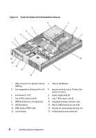 76
76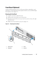 77
77 78
78 79
79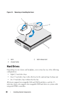 80
80 81
81