Dell S4112F S4112-ON Series Setup Guide - Page 20
ground wire, as shown., screwdriver to tighten the screws that secures the bare wires into
 |
View all Dell S4112F manuals
Add to My Manuals
Save this manual to your list of manuals |
Page 20 highlights
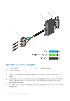
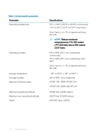
Figure 11. DC power connector and wiring block 1 Wiring block 2 3 PSU connector Power connector 1 Strip a 1/2 inch section of insulation from each of the power connector's wires, as shown. 2 Insert each of the power connector's bare wire lengths into the wiring block. The blue wire is -48V, the black wire is the positive return, and the yellow/green wire is the ground wire, as shown. 3 Use a flat-blade screwdriver to tighten the screws that secures the bare wires into the wiring block. 20 S4112-ON Series Installation
-
 1
1 -
2
-
3
-
4
-
5
-
6
-
7
-
8
-
9
-
10
-
11
-
12
-
13
-
14
-
 15
15 -
 16
16 -
 17
17 -
 18
18 -
 19
19 -
 20
20 -
 21
21 -
 22
22 -
 23
23 -
 24
24 -
 25
25 -
26
 |
 |

Figure 11. DC power connector and wiring block
1
Wiring block
2
Power connector
3
PSU connector
1
Strip a 1/2 inch section of insulation from each of the power connector’s wires, as
shown.
2
Insert each of the power connector’s bare wire lengths into the wiring block. The blue
wire is -48V, the black wire is the positive return, and the yellow/green wire is the
ground wire, as shown.
3
Use a
flat-blade
screwdriver to tighten the screws that secures the bare wires into the
wiring block.
20
S4112-ON Series Installation