Dell Vostro 1400 Service Manual - Page 44
Replacing the System Board - screen replacement
 |
View all Dell Vostro 1400 manuals
Add to My Manuals
Save this manual to your list of manuals |
Page 44 highlights
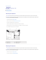
1 IO panel connector 2 speaker connector 3 system board 18. Take out the system board and keep it aside. 19. Disconnect the modem cable from the system board. 20. With the rear of the computer facing you, gently lift the system board assembly from the left side, then slide the system board assembly to the left and lift up on the right side to raise the assembly out of the computer. NOTE: It may be necessary to press outward slightly on the plastic around the connectors on the left side of the computer to lift the system board and remove it. Replacing the System Board CAUTION: Before you perform any of the procedures in this section, follow the safety instructions in the Product Information Guide. NOTICE: To avoid electrostatic discharge, ground yourself by using a wrist grounding strap or by periodically touching an unpainted metal surface, such as the back panel on the computer. 1. Follow the instructions in Before You Begin. 2. Follow the instructions in Removing the System Board. 3. For replacement of the system board, perform the steps in Removing the System Board in reverse order. NOTICE: Before turning on the computer, replace all screws and ensure that no stray screws remain inside the computer. Failure to do so may result in damage to the computer. 4. Turn on the computer. NOTE: After replacing the system board, enter the computer's alpha-numeric Service Tag into the BIOS of the replacement system board. 5. Insert the floppy disk or CD that accompanied the replacement system board into the appropriate drive. Follow the instructions that appear on the screen. Back to Contents Page
-
 1
1 -
2
-
3
-
4
-
5
-
6
-
7
-
8
-
9
-
10
-
11
-
12
-
13
-
14
-
15
-
16
-
17
-
18
-
19
-
20
-
21
-
22
-
23
-
24
-
25
-
26
-
27
-
28
-
29
-
30
-
31
-
32
-
33
-
34
-
35
-
36
-
37
-
38
-
 39
39 -
 40
40 -
 41
41 -
 42
42 -
 43
43 -
 44
44 -
 45
45
 |
 |
