Dell Vostro 15 3558 Dell Vostro 153558 Owners Manual
Dell Vostro 15 3558 Manual
 |
View all Dell Vostro 15 3558 manuals
Add to My Manuals
Save this manual to your list of manuals |
Dell Vostro 15 3558 manual content summary:
- Dell Vostro 15 3558 | Dell Vostro 153558 Owners Manual - Page 1
Dell Vostro 15-3558 Owner's Manual Regulatory Model: P52F Regulatory Type: P52F001 - Dell Vostro 15 3558 | Dell Vostro 153558 Owners Manual - Page 2
potential damage to hardware or loss of data and tells you how to avoid the problem. WARNING: A WARNING indicates a potential for property damage, personal injury, or death. Copyright © 2015 Dell Inc. All rights reserved. This product is protected by U.S. and international copyright and intellectual - Dell Vostro 15 3558 | Dell Vostro 153558 Owners Manual - Page 3
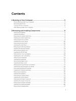
the WLAN Card...13 Installing the WLAN Card...13 Removing the Coin-Cell Battery...13 Installing the Coin-cell battery...14 Removing the Keyboard...14 Installing the Keyboard...15 Removing the Base Cover...15 Installing the Base Cover...17 Removing the Input/Output (I/O) Board 17 Installing the - Dell Vostro 15 3558 | Dell Vostro 153558 Owners Manual - Page 4
and Setup Password 42 Deleting or Changing an Existing System and/or Setup Password 43 4 Diagnostics...44 Enhanced Pre-Boot System Assessment (ePSA) Diagnostics 44 5 Specifications...45 Specifications...45 6 Contacting Dell 50 Contacting Dell...50 4 - Dell Vostro 15 3558 | Dell Vostro 153558 Owners Manual - Page 5
only perform troubleshooting and simple repairs as authorized in your product documentation, or as directed by the online or telephone service and support team. Damage due to servicing that is not authorized by Dell is not covered by your warranty. Read and follow the safety instructions that came - Dell Vostro 15 3558 | Dell Vostro 153558 Owners Manual - Page 6
turn the computer upside-down on a flat work surface. NOTE: To avoid damaging the system board, you must remove the main battery before you service the computer. 7. Remove the main battery. 8. Turn the computer top-side up. 9. Open the display. 10. Press the power button to ground the system board - Dell Vostro 15 3558 | Dell Vostro 153558 Owners Manual - Page 7
cables before turning on your computer. CAUTION: To avoid damage to the computer, use only the battery designed for this particular Dell computer. Do not use batteries designed for other Dell computers. 1. Connect any external devices, such as a port replicator or media base, and replace any cards - Dell Vostro 15 3558 | Dell Vostro 153558 Owners Manual - Page 8
This section provides detailed information on how to remove or install the components from your computer. Removing the Battery 1. Follow the procedures in Before Working Inside Your Computer. 2. Slide the release latch outwards to unlock the battery. 3. Remove the battery from the computer. 8 - Dell Vostro 15 3558 | Dell Vostro 153558 Owners Manual - Page 9
in After Working Inside Your computer . Removing the Optical-disk Drive 1. Follow the procedures in Before Working Inside Your Computer. 2. Remove the battery. 3. Perform the following steps as shown in the illustration: a. Remove the screw that secures the optical-disk drive (ODD) to the computer - Dell Vostro 15 3558 | Dell Vostro 153558 Owners Manual - Page 10
align with the screw holes at the back of the computer. 2. Tighten the screws to secure the access panel to the computer. 3. Install the battery. 4. Follow the procedures in After Working Inside Your computer . Removing the Hard Drive 1. Follow the procedures in Before Working Inside Your Computer - Dell Vostro 15 3558 | Dell Vostro 153558 Owners Manual - Page 11
b. Remove the screws that secure the hard drive to the computer [3]. 4. Perform the following steps as shown in the illustration: a. Lift the hard drive to remove it from the computer [1,2]. 5. Perform the following steps as shown in the illustration: a. Remove the screws that secure the hard drive - Dell Vostro 15 3558 | Dell Vostro 153558 Owners Manual - Page 12
the procedures in After Working Inside Your computer . Removing the Memory Module 1. Follow the procedures in Before Working Inside Your Computer. 2. Remove: a. battery b. access panel 3. Pry the securing clips away from the memory module until it pops up. 4. Remove the memory module from its socket - Dell Vostro 15 3558 | Dell Vostro 153558 Owners Manual - Page 13
procedures in After Working Inside Your computer . Removing the WLAN Card 1. Follow the procedures in Before Working Inside Your Computer. 2. Remove: a. battery b. access panel 3. Perform the following steps as shown in the illustration: a. Remove the screw that secures the WLAN card to the system - Dell Vostro 15 3558 | Dell Vostro 153558 Owners Manual - Page 14
3. Follow the procedures in After Working Inside Your computer . Removing the Keyboard 1. Follow the procedures in Before Working Inside Your Computer. 2. Remove the battery. 3. Release the keyboard by prying on the keyboard release tabs using a scribe. 4. Perform the following steps as shown in - Dell Vostro 15 3558 | Dell Vostro 153558 Owners Manual - Page 15
keyboard into the retention slots. 3. Press along the top edges to lock the keyboard in place. 4. Install the battery. 5. Follow the procedures in After Working Inside Your computer . Removing the Base Cover 1. Follow the procedures in Before Working Inside Your Computer. 2. Remove: a. battery 15 - Dell Vostro 15 3558 | Dell Vostro 153558 Owners Manual - Page 16
b. hard drive c. access panel d. optical-disk drive e. WLAN card f. memory module g. keyboard 3. Perform the following steps as shown in the illustration: a. Disconnect the ODD connector and lift it to remove it from the system board [1,2]. b. Remove the - Dell Vostro 15 3558 | Dell Vostro 153558 Owners Manual - Page 17
the computer over and tighten the screws at the base of the computer. 5. Install: a. keyboard b. memory module c. hard drive d. WLAN card e. access panel f. optical-disk drive g. battery 6. Follow the procedures in After Working Inside Your computer . Removing the Input/Output (I/O) Board 1. Follow - Dell Vostro 15 3558 | Dell Vostro 153558 Owners Manual - Page 18
Board 1. Connect the I/O board cable to the system board. 2. Install the I/O board into the chassis. 3. Install: a. base cover b. keyboard c. memory module d. hard drive e. WLAN card f. access panel g. optical-disk drive h. battery 4. Follow the procedures in After Working Inside Your computer . 18 - Dell Vostro 15 3558 | Dell Vostro 153558 Owners Manual - Page 19
Removing the Heatsink Assembly 1. Follow the procedures in Before Working Inside Your Computer. 2. Remove: a. battery b. optical-disk drive c. access panel d. hard drive e. memory module f. keyboard g. base cover 3. Perform the following steps as shown in the illustration: a. Disconnect the system - Dell Vostro 15 3558 | Dell Vostro 153558 Owners Manual - Page 20
system board. 2. Connect the system fan cable to the system board. 3. Install: a. base cover b. keyboard c. memory module d. hard drive e. WLAN card f. access panel g. optical-disk drive h. battery 4. Follow the procedures in After Working Inside Your computer . Removing the Speakers 1. Follow the - Dell Vostro 15 3558 | Dell Vostro 153558 Owners Manual - Page 21
the chassis and press along the retention clips to lock in place. 2. Install: a. base cover b. keyboard c. memory module d. hard drive e. WLAN card f. access panel g. optical-disk drive h. battery 3. Follow the procedures in After Working Inside Your computer. Removing the System Board 1. Follow the - Dell Vostro 15 3558 | Dell Vostro 153558 Owners Manual - Page 22
4. Perform the following steps as shown in the illustration: a. Lift the locking tab [1]. b. Disconnect the display assembly cable [2]. c. Unroute the display assembly cable [3]. 5. Perform the following steps as shown in the illustration: a. Remove the screw that secures the power connector to the - Dell Vostro 15 3558 | Dell Vostro 153558 Owners Manual - Page 23
system board to the computer. 3. Connect the power connector to the system board. 4. Connect the display assembly cable to the system board. 5. Install: a. base cover b. keyboard c. memory module d. hard drive 23 - Dell Vostro 15 3558 | Dell Vostro 153558 Owners Manual - Page 24
1. Insert the power connector into its slot on the chassis and guide the cable into the retention tabs. 2. Connect the power connector cable to the system board. 3. Install: a. system board b. base cover c. keyboard d. memory module e. hard drive f. access panel g. optical-disk drive h. battery 24 - Dell Vostro 15 3558 | Dell Vostro 153558 Owners Manual - Page 25
. Removing the Display Assembly 1. Follow the procedures in Before Working Inside Your Computer. 2. Remove: a. battery b. optical-disk drive c. access panel d. hard drive e. memory module f. keyboard 3. Perform the following steps as shown in the illustration: a. Lift the tab and disconnect the - Dell Vostro 15 3558 | Dell Vostro 153558 Owners Manual - Page 26
the chassis. 2. Route the WLAN and display assembly cables through their tabs and then tighten the display hinges screws to secure the display assembly. 3. Install: a. keyboard b. memory module c. hard drive d. access panel e. optical-disk drive 26 - Dell Vostro 15 3558 | Dell Vostro 153558 Owners Manual - Page 27
Removing the Display Bezel 1. Follow the procedures in Before Working Inside Your Computer. 2. Remove: a. battery b. optical-disk drive c. access panel d. hard drive e. memory module f. keyboard g. system board h. display assembly 3. Perform the following steps as shown in the illustration: a. Place - Dell Vostro 15 3558 | Dell Vostro 153558 Owners Manual - Page 28
Your computer . Removing the Camera 1. Follow the procedures in Before Working Inside Your Computer. 2. Remove: a. battery b. optical-disk drive c. access panel d. hard drive e. memory module f. keyboard g. base cover h. system board i. display assembly 3. Perform the following steps as shown in the - Dell Vostro 15 3558 | Dell Vostro 153558 Owners Manual - Page 29
. Removing the Display Hinges 1. Follow the procedures in Before Working Inside Your Computer. 2. Remove: a. battery b. optical-disk drive c. access panel d. hard drive e. memory module f. keyboard g. system board h. display assembly i. display bezel 3. Perform the following steps as shown in the - Dell Vostro 15 3558 | Dell Vostro 153558 Owners Manual - Page 30
Removing the Display Panel 1. Follow the procedures in Before Working Inside Your Computer. 2. Remove: a. battery b. optical-disk drive c. access panel d. hard drive e. memory module f. keyboard g. system board h. display assembly i. display bezel j. display hinges 3. Perform the following steps as - Dell Vostro 15 3558 | Dell Vostro 153558 Owners Manual - Page 31
5. Perform the following steps as shown in the illustration: a. Disconnect the eDP cable from the computer [1]. b. Remove the display panel from the computer [2]. Installing the Display Panel 1. Connect the display cable to the display panel. 2. Affix the tape to secure the display cable. 3. Place - Dell Vostro 15 3558 | Dell Vostro 153558 Owners Manual - Page 32
b. display bezel c. display assembly d. system board e. keyboard f. memory module g. hard drive h. access panel i. optical-disk drive j. battery 6. Follow the procedures in After Working Inside Your computer . 32 - Dell Vostro 15 3558 | Dell Vostro 153558 Owners Manual - Page 33
Sequence allows you to bypass the System Setup‐defined boot device order and boot directly to a specific device (for example: optical drive or hard drive). During the Power-on Self Test (POST), when the Dell logo appears, you can: • Access System Setup by pressing key • Bring up the one-time - Dell Vostro 15 3558 | Dell Vostro 153558 Owners Manual - Page 34
This section lists the primary hardware features of your computer. • System Information: Displays BIOS Version, Service Tag, Asset Tag, Ownership Audio Controller, Wi-Fi Device, Bluetooth Device. Battery Information Boot Sequence Displays the battery status and the type of AC adapter connected to - Dell Vostro 15 3558 | Dell Vostro 153558 Owners Manual - Page 35
is part of the SMART (Self Monitoring Analysis and Reporting Technology) specification. This option is disabled by default. • Enable SMART Reporting USB Configuration This field configures the integrated USB controller. If Boot Support is enabled, the system is allowed to boot any type of USB - Dell Vostro 15 3558 | Dell Vostro 153558 Owners Manual - Page 36
Security Option Admin Password System Password Description NOTE: USB keyboard and mouse always work in the BIOS setup irrespective of Allows you to set the display brightness depending up on the power source (On Battery and On AC). NOTE: The Video setting will only be visible when a video - Dell Vostro 15 3558 | Dell Vostro 153558 Owners Manual - Page 37
Default Setting: Allow Non-Admin Password Changes is selected. Non-Admin Setup Changes CPU XD Support Allows you to determine whether changes to the setup options are allowed when an Administrator Enable Description This option enables or disables the Secure Boot Feature. • Disabled • Enabled 37 - Dell Vostro 15 3558 | Dell Vostro 153558 Owners Manual - Page 38
, two cores will be enabled. If you disable Multi Core Support, one core will be enabled. • Enable Multi Core Support Default Setting: The option is enabled. Allows you to enable or disable the Intel SpeedStep feature. • Enable Intel SpeedStep Default Setting: The option is enabled. Allows you - Dell Vostro 15 3558 | Dell Vostro 153558 Owners Manual - Page 39
, the system setup will remove power from all of the USB ports to conserve battery power. • Enable USB Wake Support Default Setting: The option is disabled. Wake on LAN/WLAN Allows you to enable or disable the feature that powers on the computer from the Off state when triggered by a LAN signal - Dell Vostro 15 3558 | Dell Vostro 153558 Owners Manual - Page 40
mode may not be available for all the batteries. To enable this option, disable the Advanced Battery Charge Configuration option. Table 9. POST Behavior Minimal • Thorough (default) • Auto Table 10. Virtualization Support Option Description Virtualization Allows you to enable or disable the - Dell Vostro 15 3558 | Dell Vostro 153558 Owners Manual - Page 41
), on replacing the system board or if an update is available. For laptops, ensure that your computer battery is fully charged and connected to a power outlet 1. Re-start the computer. 2. Go to dell.com/support. 3. Enter the Service Tag or Express Service Code and click Submit. NOTE: To locate the - Dell Vostro 15 3558 | Dell Vostro 153558 Owners Manual - Page 42
also analyze which drivers need an update. To do this for your product, click Analyze System for Updates and follow the instructions on the screen make changes to the BIOS settings of your computer. CAUTION: The password features provide a basic level of security for the data on your computer. - Dell Vostro 15 3558 | Dell Vostro 153558 Owners Manual - Page 43
4. Type the system password that you entered earlier and click OK. 5. Select Setup Password, type your system password and press or . A message prompts you to re-type the setup password. 6. Type the setup password that you entered earlier and click OK. 7. Press and a message - Dell Vostro 15 3558 | Dell Vostro 153558 Owners Manual - Page 44
View error messages that inform you of problems encountered during testing CAUTION: Use the computer boots, press the key as the Dell logo appears. 3. On the boot menu screen, select . 4. If you wish to run a diagnostic test on a specific device, press and click Yes to stop the diagnostic - Dell Vostro 15 3558 | Dell Vostro 153558 Owners Manual - Page 45
Chipset integrated in processor DRAM bus width 64 bits Flash EPROM 8 MB Table 15. Processor Feature Processor Type L1 cache L2 cache L3 cache Description • 4th Generation Intel core i3 • 5th Generation Intel core i3/i5/i7 • Intel Celeron Dual Core • Intel Pentium Quard Core 128 KB 512 KB - Dell Vostro 15 3558 | Dell Vostro 153558 Owners Manual - Page 46
Controller: UMA Discrete Data bus: External display support Table 19. Camera Feature Camera Resolution Video Resolution (maximum) Diagonal viewing angle Table 20. Communication Feature Network adapter Wireless Table 21. Ports and Connectors Feature Audio Video Network adapter USB: 46 Description - Dell Vostro 15 3558 | Dell Vostro 153558 Owners Manual - Page 47
supports Microsoft Kernel Debugging. The ports are identified in the documentation shipped with your computer. Media card reader one SD slot Table 22. Display Feature Type Vostro 15-3558 • 15.6 inches HD WLED • 15 2265 mm Table 23. Keyboard Feature Number of keys: Description US 101, - Dell Vostro 15 3558 | Dell Vostro 153558 Owners Manual - Page 48
Type Dimensions: Height Width Depth Weight Life span Voltage Temperature range: Operating Non-Operating Coin-cell battery Table 26. AC Adapter Feature Type Input voltage Input frequency Input current (maximum) 45 W 65 W Output current 45 W 65 W Rated output voltage Temperature range: Operating - Dell Vostro 15 3558 | Dell Vostro 153558 Owners Manual - Page 49
Weight: Touch Non-Touch Table 28. Environmental Feature Temperature: Operating Storage Relative humidity (maximum): Operating °F) 10 % to 90 % (non-condensing) 0 % to 95 % (non-condensing) -15.2 m to 3048 m (-50 to 10,000 ft) 0° to 35°C -15.2 m to 10,668 m (-50 ft to 35,000 ft) G1 as defined by ISA- - Dell Vostro 15 3558 | Dell Vostro 153558 Owners Manual - Page 50
options. Availability varies by country and product, and some services may not be available in your area. To contact Dell for sales, technical support, or customer service issues: 1. Go to dell.com/support. 2. Select your support category. 3. Verify your country or region in the Choose a Country
-
 1
1 -
 2
2 -
 3
3 -
 4
4 -
 5
5 -
 6
6 -
 7
7 -
8
-
9
-
10
-
11
-
12
-
13
-
14
-
15
-
16
-
17
-
18
-
19
-
20
-
21
-
22
-
23
-
24
-
25
-
26
-
27
-
28
-
29
-
30
-
31
-
32
-
33
-
34
-
35
-
36
-
37
-
38
-
39
-
40
-
41
-
42
-
43
-
44
-
45
-
46
-
47
-
48
-
49
-
50
 |
 |

Dell Vostro 15–3558
Owner's Manual
Regulatory Model: P52F
Regulatory Type: P52F001