Dell Vostro 15 3558 Dell Vostro 153558 Owners Manual - Page 24
Removing the Power Connector, Installing the Power Connector
 |
View all Dell Vostro 15 3558 manuals
Add to My Manuals
Save this manual to your list of manuals |
Page 24 highlights
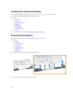
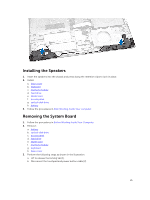
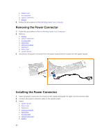
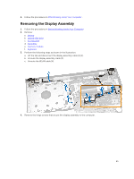
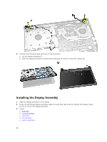
e. WLAN card f. access panel g. optical-disk drive h. battery 6. Follow the procedures in After Working Inside Your computer. Removing the Power Connector 1. Follow the procedures in Before Working Inside Your Computer. 2. Remove: a. battery b. optical-disk drive c. access panel d. hard drive e. memory module f. keyboard g. base cover h. system board 3. Disconnect the power connector from the system board and lift it away from the system board. Installing the Power Connector 1. Insert the power connector into its slot on the chassis and guide the cable into the retention tabs. 2. Connect the power connector cable to the system board. 3. Install: a. system board b. base cover c. keyboard d. memory module e. hard drive f. access panel g. optical-disk drive h. battery 24
-
 1
1 -
2
-
3
-
4
-
5
-
6
-
7
-
8
-
9
-
10
-
11
-
12
-
13
-
14
-
15
-
16
-
17
-
18
-
 19
19 -
 20
20 -
 21
21 -
 22
22 -
 23
23 -
 24
24 -
 25
25 -
 26
26 -
 27
27 -
 28
28 -
 29
29 -
30
-
31
-
32
-
33
-
34
-
35
-
36
-
37
-
38
-
39
-
40
-
41
-
42
-
43
-
44
-
45
-
46
-
47
-
48
-
49
-
50
 |
 |