Dell Vostro 3546 Owners Manual - Page 28
Remove the screws that secure the display hinges to the display assembly. Then, lift and remove
 |
View all Dell Vostro 3546 manuals
Add to My Manuals
Save this manual to your list of manuals |
Page 28 highlights
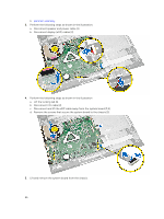
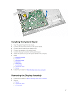
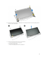
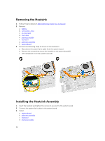
d. hard drive e. memory module f. keyboard g. palmrest assembly h. system board 3. Unroute the WLAN cable and remove the screws that secure the display panel to the chassis. 4. Place the display panel on a stable surface and lift the bezel from the computer. 5. Remove the screws that secure the display hinges to the display assembly. Then, lift and remove the display hinges away from the display assembly. 28
-
 1
1 -
2
-
3
-
4
-
5
-
6
-
7
-
8
-
9
-
10
-
11
-
12
-
13
-
14
-
15
-
16
-
17
-
18
-
19
-
20
-
21
-
22
-
 23
23 -
 24
24 -
 25
25 -
 26
26 -
 27
27 -
 28
28 -
 29
29 -
 30
30 -
 31
31 -
 32
32 -
 33
33 -
34
-
35
-
36
-
37
-
38
-
39
-
40
-
41
-
42
-
43
-
44
-
45
-
46
-
47
-
48
-
49
-
50
 |
 |

d.
hard drive
e.
memory module
f.
keyboard
g.
palmrest assembly
h.
system board
3.
Unroute the WLAN cable and remove the screws that secure the display panel to the chassis.
4.
Place the display panel on a stable surface and lift the bezel from the computer.
5.
Remove the screws that secure the display hinges to the display assembly. Then, lift and remove the
display hinges away from the display assembly.
28