Dell Vostro 3590 With optical drive Service Manual
Dell Vostro 3590 Manual
 |
View all Dell Vostro 3590 manuals
Add to My Manuals
Save this manual to your list of manuals |
Dell Vostro 3590 manual content summary:
- Dell Vostro 3590 | With optical drive Service Manual - Page 1
Dell Vostro 3590 (With optical drive) Service Manual Regulatory Model: P75F Regulatory Type: P75F010 - Dell Vostro 3590 | With optical drive Service Manual - Page 2
and tells you how to avoid the problem. WARNING: A WARNING indicates a potential for property damage, personal injury, or death. © 2018 - 2019 Dell Inc. or its subsidiaries. All rights reserved. Dell, EMC, and other trademarks are trademarks of Dell Inc. or its subsidiaries. Other trademarks may - Dell Vostro 3590 | With optical drive Service Manual - Page 3
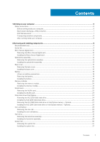
Contents 1 Working on your computer...6 Safety instructions...6 Before working inside your computer...6 Electrostatic discharge-ESD protection...7 ESD field service kit ...7 Transporting sensitive components...8 After working inside your computer...8 2 Removing and installing components 9 - Dell Vostro 3590 | With optical drive Service Manual - Page 4
Heat sink...39 Removing the heatsink...39 Installing the heatsink...39 VGA Daughterboard...40 Removing the VGAcable...40 Installing the VGA cable...41 Speakers...42 Removing the speakers...42 Installing the speakers...43 IO board...44 Removing the IO board...44 Installing the IO board...46 Touchpad - Dell Vostro 3590 | With optical drive Service Manual - Page 5
support...86 Wireless...86 Maintenance screen...86 System logs...87 SupportAssist System Resolution...87 System and setup password...87 Assigning a system setup password...87 Deleting or changing an existing system setup password 88 4 Troubleshooting help...92 Contacting Dell...92 Contents 5 - Dell Vostro 3590 | With optical drive Service Manual - Page 6
only perform troubleshooting and simple repairs as authorized in your product documentation, or as directed by the online or telephone service and support team. Damage due to servicing that is not authorized by Dell is not covered by your warranty. Read and follow the safety instructions that came - Dell Vostro 3590 | With optical drive Service Manual - Page 7
such as intermittent problems or a shortened Dell products, the sensitivity to static damage is now higher than in previous Dell and immediately generates a "No damage to recognize and troubleshoot is the intermittent (also is known as bonding. Use only Field Service kits with a wrist strap, mat, - Dell Vostro 3590 | With optical drive Service Manual - Page 8
service technicians use the traditional wired ESD grounding wrist strap and protective anti-static mat at all times when servicing Dell stable base, and point your toes out. 2. Tighten stomach muscles. Abdominal muscles support your spine when you lift, offsetting the force of the load. 3. Lift with - Dell Vostro 3590 | With optical drive Service Manual - Page 9
procedures in this document require the following tools: • Phillips #0 screwdriver • Phillips #1 screwdriver • Plastic scribe NOTE: The #0 screw driver is for screws 0-1 and the #1 screw driver is for screws 2-4 Screw list The table provides the list of screws that are used for securing different - Dell Vostro 3590 | With optical drive Service Manual - Page 10
Component I/O board Optical-drive assembly Screw type M2x4 M2x4 Quantity 1 Screw image Optical-drive bracket M2x3 2 Optical-drive connector board M2x2 Big Head 1 Power-adapter port Power-button board M2x3 1 M2x2 Big Head 1 Power button with fingerprint M2x2 Big Head 1 reader ( - Dell Vostro 3590 | With optical drive Service Manual - Page 11
Installing the Micro Secure Digital card Steps 1. Slide the micro secure digital into the slot until it clicks into place. 2. Follow the procedures in After working inside your computer. Removing and installing components 11 - Dell Vostro 3590 | With optical drive Service Manual - Page 12
Optical drive assembly Removing the optical drive assembly Prerequisites 1. Follow the procedure in before working inside your computer 2. Remove the SD memory card Steps 1. Remove the single (M2x4) screw that secures the optical drive to the system [1]. 2. Slide the optical drive out of the - Dell Vostro 3590 | With optical drive Service Manual - Page 13
3. Remove the two (M2x3) screws that secure the optical drive bracket to the optical drive [1]. 4. Remove the optical drive bracket from the optical drive [2]. Installing the optical drive assembly Steps 1. Align the optical drive bracket to the screw holes on the optical drive [1]. 2. Replace the - Dell Vostro 3590 | With optical drive Service Manual - Page 14
3. Insert the optical drive into the slot until it clicks into place [1]. 4. Replace the single (M2x4) screw that secures the optical drive to the system [2]. Next steps 1. Replace the SD memory card 2. Follow the procedure in after working inside your computer 14 Removing and installing components - Dell Vostro 3590 | With optical drive Service Manual - Page 15
Base cover Removing the base cover Prerequisites 1. Follow the procedure in before working inside your computer 2. Remove the SD memory card 3. Remove the optical drive assembly Steps 1. Loosen the three captive screws [1]. 2. Remove the single (M2x4) screw, two (M2x2) screws, and six (M2.5x7) - Dell Vostro 3590 | With optical drive Service Manual - Page 16
Installing the base cover Steps 1. Place the base cover on the palmrest and keyboard assembly [1]. 2. Press the right side of the base cover until it snaps into place [2, 3]. 16 Removing and installing components - Dell Vostro 3590 | With optical drive Service Manual - Page 17
3. Tighten the three captive screws, and replace the single (M2x4) screw that secures the base cover to the palmrest and keyboard assembly [1, 2]. 4. Replace the two (M2x2) screws, and six (M2.5x7) screws that secure the base cover to the palmrest and keyboard assembly [3, 4]. Removing and - Dell Vostro 3590 | With optical drive Service Manual - Page 18
battery. • Ensure any screws during the servicing of this product are not lost or , contact for assistance and further instructions. • If the battery gets Dell technical support for assistance. See www.dell.com/contactdell. • Always purchase genuine batteries from www.dell.com or authorized Dell - Dell Vostro 3590 | With optical drive Service Manual - Page 19
Installing the battery Steps 1. Align the screw holes on the battery with the screw holes on the palmrest and keyboard assembly [1]. 2. Replace the four (M2x3) screws that secure the battery to the palmrest and keyboard assembly [2]. 3. Connect the battery cable to the system board [3]. Removing - Dell Vostro 3590 | With optical drive Service Manual - Page 20
Next steps 1. Replace the base cover 2. Replace the optical drive assembly 3. Replace the SD memory card 4. Follow the procedure in after working inside your computer Memory modules Removing the memory module Prerequisites 1. Follow the procedure in before working inside your computer 2. Remove the - Dell Vostro 3590 | With optical drive Service Manual - Page 21
Installing the memory module Steps 1. Align the notch on the memory module with the tab on the memory-module slot. 2. Slide the memory module firmly into the slot at an angle [1]. 3. Press the memory module down until the clips secure it [2]. NOTE: If you do not hear the click, remove the memory - Dell Vostro 3590 | With optical drive Service Manual - Page 22
Next steps 1. Connect the battery cable to the connector on the system board. 2. Replace the base cover 3. Replace the optical drive assembly 4. Replace the SD memory card 5. Follow the procedure in after working inside your computer WLAN card Removing the WLAN card Prerequisites 1. Follow the - Dell Vostro 3590 | With optical drive Service Manual - Page 23
Installing the WLAN card About this task CAUTION: To avoid damage to the WLAN card, do not place any cables under it. Steps 1. Insert the WLAN card into the connector on the system board [1]. 2. Connect the WLAN cables to the connectors on the WLAN card [2]. 3. Place the WLAN card bracket to secure - Dell Vostro 3590 | With optical drive Service Manual - Page 24
Next steps 1. Connect the battery cable to the connector on the system board. 2. Replace the base cover 3. Replace the optical drive assembly 4. Replace the SD memory card 5. Follow the procedure in after working inside your computer Solid-state drive/Intel Optane Removing the M.2 2230 Solid-state - Dell Vostro 3590 | With optical drive Service Manual - Page 25
4. Turn the thermal plate over. 5. Remove the single (M2x2) screw that secures the solid-state drive to the thermal plate [1]. 6. Lift the solid-state drive off the thermal plate [2]. Removing and installing components 25 - Dell Vostro 3590 | With optical drive Service Manual - Page 26
Installing the M.2 2230 Solid-state drive Steps 1. Place the solid-state drive into the thermal plate slot [1]. 2. Replace the single (M2x2) screw that secures the solid-state drive to the thermal plate [2]. 3. Align the notch on the solid-state drive with the tab on the solid-state drive slot. 4. - Dell Vostro 3590 | With optical drive Service Manual - Page 27
Next steps 1. Connect the battery cable to the connector on the system board. 2. Replace the base cover 3. Replace the optical drive assembly 4. Replace the SD memory card 5. Follow the procedure in after working inside your computer Removing the M.2 2280 Solid-state drive or Intel Optane memory - - Dell Vostro 3590 | With optical drive Service Manual - Page 28
Installing the M.2 2280 Solid-state drive or Intel Optane memory - Optional Steps 1. Slide and insert the tab of the solid-state drive/Intel Optane into the solid-state drive/Intel Optane slot [1, 2]. 2. Tighten the captive screw that secures the thermal plate to the palmrest and keyboard assembly - Dell Vostro 3590 | With optical drive Service Manual - Page 29
Next steps 1. Connect the battery cable to the connector on the system board. 2. Replace the base cover 3. Replace the optical drive assembly 4. Replace the SD memory card 5. Follow the procedure in after working inside your computer Coin-cell battery Removing the coin-cell Prerequisites 1. Follow - Dell Vostro 3590 | With optical drive Service Manual - Page 30
Installing the coin-cell battery Steps 1. With the positive-side facing up, insert the coin-cell battery into the battery socket on the I/O board [1]. 2. Press the battery until it clicks into place [2]. 30 Removing and installing components - Dell Vostro 3590 | With optical drive Service Manual - Page 31
Next steps 1. Connect the battery cable to the connector on the system board. 2. Replace the base cover 3. Replace the optical drive assembly 4. Replace the SD memory card 5. Follow the procedure in after working inside your computer Hard drive Removing the hard drive assembly Prerequisites 1. - Dell Vostro 3590 | With optical drive Service Manual - Page 32
4. Disconnect the interposer from the hard drive. 5. Remove the four (M3x3) screws that secure the hard drive bracket to the hard drive [1]. 6. Lift the hard drive bracket off the hard drive [2]. 32 Removing and installing components - Dell Vostro 3590 | With optical drive Service Manual - Page 33
Installing the hard drive assembly Steps 1. Align the screw holes on the hard drive bracket with the screw holes on the hard drive [1]. 2. Replace the four (M3x3) screws that secure the hard drive bracket to the hard drive [2]. 3. Connect the interposer to the hard drive. Removing and installing - Dell Vostro 3590 | With optical drive Service Manual - Page 34
4. Align the screw holes on the hard drive assembly with the screw holes on the palm rest and keyboard assembly [1]. 5. Replace the four (M2x3) screws that secure the hard drive assembly to the palm rest and keyboard assembly [2]. 6. Connect the hard drive cable to the system board and close the - Dell Vostro 3590 | With optical drive Service Manual - Page 35
on the system board. Steps 1. Disconnect the ODD cable, display cable and fan cable from the system board [1, 2, 3]. 2. Unroute the display cable from the routing guides on the fan [1]. Removing and installing components 35 - Dell Vostro 3590 | With optical drive Service Manual - Page 36
3. Remove the three (M2.5x5) screws that secure the fan to the palm rest and keyboard board assembly [1]. 4. Lift the fan off the palm rest and keyboard board assembly [2]. 36 Removing and installing components - Dell Vostro 3590 | With optical drive Service Manual - Page 37
[1]. 2. Replace the three (M2.5x5) screws that secure the fan to the palm rest and keyboard board assembly [2]. 3. Route the display cable through the routing guides on the fan [1]. Removing and installing components 37 - Dell Vostro 3590 | With optical drive Service Manual - Page 38
4. Connect the ODD cable, display cable and fan cable to the system board [3,2,1]. Next steps 1. Replace the battery 2. Replace the base cover 3. Replace the optical drive assembly 38 Removing and installing components - Dell Vostro 3590 | With optical drive Service Manual - Page 39
4. Replace the SD memory card 5. Follow the procedure in after working inside your computer Heat sink Removing the heatsink Prerequisites 1. Follow the procedure in before working inside your computer 2. Remove the SD memory card 3. Remove the optical drive assembly 4. Remove the base cover 5. - Dell Vostro 3590 | With optical drive Service Manual - Page 40
2. Replace the three (M2x3) screws that secure the heatsink to the system board [2]. 3. In sequential order (as indicated on the heatsink), tighten the four captive screws that secure the heatsink to the system board [3]. Next steps 1. Connect the battery cable to the connector on the system board. - Dell Vostro 3590 | With optical drive Service Manual - Page 41
13. Remove the IO board 14. Remove the display assembly 15. Remove the system board Steps Disconnect the VGA cable and remove it from the palmrest and keyboard assembly [1]. Installing the VGA cable Steps Connect the VGA cable and affix it to the palmrest and keyboard assembly [1]. Removing and - Dell Vostro 3590 | With optical drive Service Manual - Page 42
Next steps 1. Replace the system board 2. Replace the display assembly 3. Replace the IO board 4. Replace the heatsink 5. Replace the system fan 6. Replace the hard drive assembly 7. Replace the coin cell battery 8. Replace the SSD 9. Replace the WLAN 10. Replace the memory 11. Connect the battery - Dell Vostro 3590 | With optical drive Service Manual - Page 43
posts and rubber grommets, place the speakers in the slots on the palm rest and keyboard assembly [1]. 2. Route the speaker cable through the routing guides on the palm rest and keyboard assembly [2]. 3. Connect the speaker cable to the system board [3]. Removing and installing components 43 - Dell Vostro 3590 | With optical drive Service Manual - Page 44
Next steps 1. Replace the M.2 SSD 2. Replace the battery 3. Replace the base cover 4. Replace the optical drive assembly 5. Replace the SD memory card 6. Follow the procedure in after working inside your computer IO board Removing the IO board Prerequisites 1. Follow the procedure in before working - Dell Vostro 3590 | With optical drive Service Manual - Page 45
3. Remove the single (M2x4) screw that secures the I/O board to the palm rest and keyboard assembly [1]. 4. Lift the I/O board, along with the cable, off the palm rest and keyboard assembly [2]. NOTE: When the IO board cable is disconnected from the system board, an RTC error occurs. This error - Dell Vostro 3590 | With optical drive Service Manual - Page 46
An "Invalid Configuration" error message is displayed prompting you to enter the BIOS and configure the date and time. The computer starts functioning normally after setting the date and time. Installing the IO board Steps 1. Using the alignment posts, place the I/O board on the palm rest and - Dell Vostro 3590 | With optical drive Service Manual - Page 47
Next steps 1. Replace the hard drive assembly 2. Replace the battery 3. Replace the base cover 4. Replace the optical drive assembly 5. Replace the SD memory card 6. Follow the procedure in after working inside your computer Touchpad Removing the touch pad assembly Prerequisites 1. Follow the - Dell Vostro 3590 | With optical drive Service Manual - Page 48
3. Remove the two (M2x2) screws that secure the touch pad bracket to the palmrest and keyboard assembly [1]. 4. Lift the touch pad bracket off the palm rest and keyboard assembly [2]. 5. Remove the four (M2x2) screws that secure the touch pad to the palmrest and keyboard assembly [1]. 6. Lift the - Dell Vostro 3590 | With optical drive Service Manual - Page 49
Installing the touch pad assembly About this task NOTE: Ensure that the touch pad is aligned with the guides available on the palm-rest and keyboard assembly, and the gap on either sides of the touch pad is equal. Steps 1. Place the touch pad - Dell Vostro 3590 | With optical drive Service Manual - Page 50
3. Place the touch pad bracket into the slot on the palmrest and keyboard assembly [1]. 4. Replace the two screws (M2x2) that secure the touch pad bracket to the palmrest and keyboard assembly [2]. 5. Affix the tape that secures the touch pad to the palmrest and keyboard assembly [1]. 6. Slide the - Dell Vostro 3590 | With optical drive Service Manual - Page 51
display cable from the system board [1, 2]. 2. Peel off the tape securing the wireless antenna from the system board [3]. 3. Unroute the display cable from the routing guides on the palmrest and keyboard assembly [4]. Removing and installing components 51 - Dell Vostro 3590 | With optical drive Service Manual - Page 52
4. Remove the five (M2.5x5) screws that secure the left and right hinges to the system board, and palmrest and keyboard assembly [1]. 5. Lift the palmrest and keyboard assembly at an angle [2]. 6. Lift the hinges and remove the palmrest and keyboard assembly off the display assembly [1, 2]. 52 - Dell Vostro 3590 | With optical drive Service Manual - Page 53
7. After performing all the preceding steps, you are left with display assembly. Removing and installing components 53 - Dell Vostro 3590 | With optical drive Service Manual - Page 54
Installing the display assembly About this task NOTE: Ensure that the hinges are opened to the maximum before replacing the display assembly on the palmrest and keyboard assembly. Steps 1. Align and place the palmrest and keyboard assembly under the hinges on the display assembly [1]. 2. Seat the - Dell Vostro 3590 | With optical drive Service Manual - Page 55
5. Route the display cable through the routing guides on the palmrest and keyboard assembly [1]. 6. Affix the antenna cables to the system board [2]. 7. Connect the display cable and the optical drive cable to the connector on the system board [3, 4]. Removing and installing components 55 - Dell Vostro 3590 | With optical drive Service Manual - Page 56
Next steps 1. Replace the WLAN 2. Connect the battery cable to the connector on the system board. 3. Replace the base cover 4. Replace the optical drive assembly 5. Replace the SD memory card 6. Follow the procedure in after working inside your computer Power-button board Removing the power button - Dell Vostro 3590 | With optical drive Service Manual - Page 57
Installing the power button board Steps 1. Place the power-button board into the slot on the palmrest and keyboard assembly [1]. 2. Replace the single (M2x2) screw that secures the power button board to the palmrest and keyboard assembly [2]. 3. Affix the conductive tape to the power button board - Dell Vostro 3590 | With optical drive Service Manual - Page 58
5. Remove the memory 6. Remove the WLAN 7. Remove the SSD 8. Remove the system fan 9. Remove the heatsink 10. Remove the display assembly Steps 1. Disconnect the power adapter port cable and speaker cable from the system board [1, 2]. 2. Disconnect the following cables from the system board: a) - Dell Vostro 3590 | With optical drive Service Manual - Page 59
2. Remove the SD memory card 3. Remove the optical drive assembly 4. Remove the base cover 5. Remove the battery 6. Remove the WLAN 7. Remove the SSD 8. Remove the system fan 9. Remove the heatsink 10. Remove the display assembly 11. Remove the power button board 12. Remove the system board Steps 1. - Dell Vostro 3590 | With optical drive Service Manual - Page 60
Next steps 1. Replace the system board 2. Replace the power button board 3. Replace the display assembly 4. Replace the heatsink 5. Replace the system fan 6. Replace the SSD 7. Replace the WLAN 8. Replace the battery 9. Replace the base cover 10. Replace the optical drive assembly 11. Replace the SD - Dell Vostro 3590 | With optical drive Service Manual - Page 61
Steps 1. Disconnect and route the power adapter cable from the system board [1, 2]. 2. Remove the single (M2x3) screw that secures the power adapter port to the palmrest and keyboard assembly [3]. 3. Lift the power adapter port, along with its cable, off the palmrest and keyboard assembly [4]. - Dell Vostro 3590 | With optical drive Service Manual - Page 62
Next steps 1. Replace the power button board 2. Replace the display assembly 3. Replace the SSD 4. Replace the WLAN 5. Replace the battery 6. Replace the base cover 7. Replace the optical drive assembly 8. Replace the SD memory card 9. Follow the procedure in after working inside your computer - Dell Vostro 3590 | With optical drive Service Manual - Page 63
Steps 1. Pry the inner top side of the display bezel [1]. 2. Continue to pry the inner left and inner right edges of the display bezel [2]. 3. Pry up the bottom inner edge of the display bezel and lift the bezel off the display assembly [3]. Installing the display bezel Steps Align the display - Dell Vostro 3590 | With optical drive Service Manual - Page 64
Next steps 1. Replace the display assembly 2. Replace the hard drive assembly 3. Replace the system fan 4. Replace the heatsink 5. Replace the SSD 6. Replace the WLAN 7. Replace the memory 8. Connect the battery cable to the connector on the system board. 9. Replace the base cover 10. Replace the - Dell Vostro 3590 | With optical drive Service Manual - Page 65
10. Remove the heatsink 11. Remove the display assembly 12. Remove the display bezel Steps 1. Using a plastic scribe, gently pry the camera off the display back-cover and antenna assembly [1]. 2. Disconnect the camera cable from the camera module [2]. 3. Lift the camera module from the display back- - Dell Vostro 3590 | With optical drive Service Manual - Page 66
Next steps 1. Replace the display bezel 2. Replace the display assembly 3. Replace the hard drive assembly 4. Replace the system fan 5. Replace the heatsink 6. Replace the SSD 7. Replace the WLAN 8. Replace the battery 9. Replace the base cover 10. Replace the optical drive assembly 11. Replace the - Dell Vostro 3590 | With optical drive Service Manual - Page 67
7. Remove the SSD 8. Remove the hard drive assembly 9. Remove the system fan 10. Remove the heatsink 11. Remove the display assembly 12. Remove the display bezel 13. Remove the camera Steps 1. Remove the four (M2x2) screws that secure the display panel to the display back-cover and antenna assembly - Dell Vostro 3590 | With optical drive Service Manual - Page 68
Installation display panel Steps 1. Place the display panel on a flat and clean surface [1]. 2. Connect the display cable to the connector at the back of the display panel and close the latch to secure the cable [2]. 3. Adhere the tape that secures the display cable to the back of the display panel - Dell Vostro 3590 | With optical drive Service Manual - Page 69
5. Align the screw holes on the display panel with the screw holes on the display back-cover and antenna assembly. 6. Replace the four (M2x2) screws that secure the display panel to the display back-cover and antenna assembly [1]. Removing and installing components 69 - Dell Vostro 3590 | With optical drive Service Manual - Page 70
Next steps 1. Replace the camera 2. Replace the display bezel 3. Replace the display assembly 4. Replace the hard drive assembly 5. Replace the system fan 6. Replace the heatsink 7. Replace the SSD 8. Replace the WLAN 9. Replace the battery 10. Replace the base cover 11. Replace the optical drive - Dell Vostro 3590 | With optical drive Service Manual - Page 71
Installing the display hinges Steps 1. Align the screw holes on the hinges and brackets with the screw holes on the display back-cover and antenna assembly [1]. 2. Replace the eight (M2.5x2.5) screws and two (M2x2) screws that secure the hinges to the display back-cover and antenna assembly [2, 3]. - Dell Vostro 3590 | With optical drive Service Manual - Page 72
Next steps 1. Replace the display panel 2. Replace the camera 3. Replace the display bezel 4. Replace the display assembly 5. Replace the hard drive assembly 6. Replace the system fan 7. Replace the heatsink 8. Replace the SSD 9. Replace the WLAN 10. Replace the battery 11. Replace the base cover 12 - Dell Vostro 3590 | With optical drive Service Manual - Page 73
display bezel 13. Remove the display panel 14. Remove the display hinges Steps 1. Remove the camera cable and the display cable from the routing guides on the display back-cover and antenna assembly [1]. 2. Peel the adhesive that secures the camera cable [2]. 3. Lift the camera cable and the display - Dell Vostro 3590 | With optical drive Service Manual - Page 74
Next steps 1. Replace the display hinges 2. Replace the display panel 3. Replace the display bezel 4. Replace the display assembly 5. Replace the hard drive assembly 6. Replace the system fan 7. Replace the heatsink 8. Replace the SSD 9. Replace the WLAN 10. Replace the battery 11. Replace the base - Dell Vostro 3590 | With optical drive Service Manual - Page 75
6. Remove the WLAN 7. Remove the SSD 8. Remove the hard drive assembly 9. Remove the system fan 10. Remove the heatsink 11. Remove the display assembly 12. Remove the display bezel 13. Remove the camera 14. Remove the display panel 15. Remove the display hinges 16. Remove the display cable About - Dell Vostro 3590 | With optical drive Service Manual - Page 76
Installing the display back-cover About this task Place the display back-cover on a clean and flat surface. Next steps 1. Replace the display cable 2. Replace the display hinges 3. Replace the display panel 4. Replace the camera 5. Replace the display bezel 6. Replace the display assembly 7. Replace - Dell Vostro 3590 | With optical drive Service Manual - Page 77
Palm-rest and keyboard assembly Removing the palmrest and keyboard assembly Prerequisites 1. Follow the procedure in before working inside your computer 2. Remove the SD memory card 3. Remove the optical drive assembly 4. Remove the base cover 5. Remove the battery 6. Remove the memory 7. Remove the - Dell Vostro 3590 | With optical drive Service Manual - Page 78
78 Removing and installing components - Dell Vostro 3590 | With optical drive Service Manual - Page 79
Manage your computer security Topics: • Boot menu • Navigation keys • System setup options • System and setup password Boot menu Press when the Dell logo appears to initiate a one-time boot menu with a list of the valid boot devices for the system. Diagnostics and BIOS Setup options are also - Dell Vostro 3590 | With optical drive Service Manual - Page 80
System Information: Displays BIOS Version, Service Tag, Asset Tag, Ownership Tag, Ownership Date, Manufacture Date, and the Express Service Code. • Memory Information: = SATA is configured for AHCI mode • RAID ON = SATA is configured to support RAID mode (selected by default) 80 System setup - Dell Vostro 3590 | With optical drive Service Manual - Page 81
. The Enable Smart Reporting option is disabled by default. Allows you to enable or disable the integrated USB controller for: • Enable USB Boot Support • Enable External USB Port All the options are enabled by default. Allows you to enable or disable the integrated audio controller. The option - Dell Vostro 3590 | With optical drive Service Manual - Page 82
option will block BIOS updates from services such as Microsoft Windows Update and Linux Vendor Firmware Service (LVFS) Allows you to control This option is not set by default. Allows you to disable master password support Hard Disk passwords need to be cleared before the settings can be changed. - Dell Vostro 3590 | With optical drive Service Manual - Page 83
the behavior of Secure Boot to allow evaluation or enforcement of UEFI driver signatures. • Deployed Mode (default) • Audit Mode Allows you to MB • 128 MB-Default Performance Table 7. Performance Option Multi Core Support Description This field specifies whether the process has one or all cores - Dell Vostro 3590 | With optical drive Service Manual - Page 84
• Every Day • Weekdays • Select Days Default setting: Disabled USB Wake Support Allows you to enable USB devices to wake the system from Standby. NOTE from all the USB ports to conserve battery power. • Enable USB Wake Support Wake on WLAN Allows you to enable or disable the feature that powers - Dell Vostro 3590 | With optical drive Service Manual - Page 85
are: • Adaptive-enabled by default • Standard-Fully charges your battery at a standard rate. • ExpressCharge-The battery charges over a shorter time using Dell's fast charging technology. • Primarily AC use • Custom If Custom Charge is selected, you can also configure Custom Charge Start and Custom - Dell Vostro 3590 | With optical drive Service Manual - Page 86
Virtualization support Option Description Virtualization This field specifies whether a the options are enabled by default. Maintenance screen Option Service Tag Asset Tag BIOS Downgrade Data Wipe BIOS Recovery Description Displays the Service Tag of your computer. Allows you to create a - Dell Vostro 3590 | With optical drive Service Manual - Page 87
System logs Option BIOS Events Thermal Events Power Events Description Allows you to view and clear the System Setup (BIOS) POST events. Allows you to view and clear the System Setup (Thermal) events. Allows you to view and clear the System Setup (Power) events. SupportAssist System Resolution - Dell Vostro 3590 | With optical drive Service Manual - Page 88
• The password can contain the numbers 0 through 9. • Only lower case letters are valid, upper case letters are not allowed. • Only the following special characters are allowed: space 3. Type the system password that you entered earlier in the Confirm new password field and click OK. 4. Press Esc - Dell Vostro 3590 | With optical drive Service Manual - Page 89
successfully • View error messages that inform you of problems encountered during testing NOTE: Some tests for specific are displayed. Note the error code and validation number and contact Dell. System diagnostic lights Battery-status light Indicates the power and battery . Troubleshooting 89 - Dell Vostro 3590 | With optical drive Service Manual - Page 90
knowledge base article SLN143196 at www.dell.com/support. 3. Copy the BIOS setup instructions on the screen to complete the BIOS update. Flashing the BIOS About this task You may need to flash (update) the BIOS when an update is available or when you replace the system board. 90 Troubleshooting - Dell Vostro 3590 | With optical drive Service Manual - Page 91
on your computer. 2. Go to www.dell.com/support. 3. Click Product support, enter the Service Tag of your computer, and then click Submit. NOTE: If you do not have the Service Tag, use the auto-detect feature or manually browse for your computer model. 4. Click Drivers & downloads > Find it myself - Dell Vostro 3590 | With optical drive Service Manual - Page 92
. Availability varies by country and product, and some services may not be available in your area. To contact Dell for sales, technical support, or customer service issues: Steps 1. Go to Dell.com/support. 2. Select your support category. 3. Verify your country or region in the Choose a Country
-
 1
1 -
 2
2 -
 3
3 -
 4
4 -
 5
5 -
 6
6 -
 7
7 -
8
-
9
-
10
-
11
-
12
-
13
-
14
-
15
-
16
-
17
-
18
-
19
-
20
-
21
-
22
-
23
-
24
-
25
-
26
-
27
-
28
-
29
-
30
-
31
-
32
-
33
-
34
-
35
-
36
-
37
-
38
-
39
-
40
-
41
-
42
-
43
-
44
-
45
-
46
-
47
-
48
-
49
-
50
-
51
-
52
-
53
-
54
-
55
-
56
-
57
-
58
-
59
-
60
-
61
-
62
-
63
-
64
-
65
-
66
-
67
-
68
-
69
-
70
-
71
-
72
-
73
-
74
-
75
-
76
-
77
-
78
-
79
-
80
-
81
-
82
-
83
-
84
-
85
-
86
-
87
-
88
-
89
-
90
-
91
-
92
 |
 |

Dell Vostro 3590 (With optical drive)
Service Manual
Regulatory Model: P75F
Regulatory Type: P75F010