Dell Vostro 7620 Service Manual
Dell Vostro 7620 Manual
 |
View all Dell Vostro 7620 manuals
Add to My Manuals
Save this manual to your list of manuals |
Dell Vostro 7620 manual content summary:
- Dell Vostro 7620 | Service Manual - Page 1
Vostro 7620 Service Manual Regulatory Model: P117F Regulatory Type: P117F003 April 2022 Rev. A00 - Dell Vostro 7620 | Service Manual - Page 2
and tells you how to avoid the problem. WARNING: A WARNING indicates a potential for property damage, personal injury, or death. © 2022 Dell Inc. or its subsidiaries. All rights reserved. Dell Technologies, Dell, and other trademarks are trademarks of Dell Inc. or its subsidiaries. Other trademarks - Dell Vostro 7620 | Service Manual - Page 3
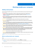
Chapter 1: Working inside your computer 6 Safety instructions...6 Before working inside your computer...6 After working inside your computer...9 Chapter 2: Removing and installing components 10 Recommended tools...10 Screw list...10 Major components of Vostro 7620...11 Base cover...13 Removing the - Dell Vostro 7620 | Service Manual - Page 4
Ubuntu...71 Updating the BIOS from the F12 One-Time boot menu 72 Chapter 5: Troubleshooting...73 Handling swollen Lithium-ion batteries...73 Locate the Service Tag or Express Service Code of your Dell computer 73 System-diagnostic lights...74 SupportAssist diagnostics...75 Built-in self-test (BIST - Dell Vostro 7620 | Service Manual - Page 5
LCD Built-in Self Test (BIST)...76 Recovering the operating system...76 WiFi power cycle...76 Contents 5 - Dell Vostro 7620 | Service Manual - Page 6
troubleshooting and repairs as authorized or directed by the Dell technical assistance team. Damage due to servicing that is not authorized by Dell is not covered by your warranty. See the safety instructions caution when handling Lithium-ion batteries in laptops. Swollen batteries should not be used - Dell Vostro 7620 | Service Manual - Page 7
it into Service Mode or the computer does not support Service Mode then proceed the power button for 3 seconds or until the Dell logo appears on the screen. b. Press any key obvious, such as intermittent problems or a shortened product life damage to recognize and troubleshoot is the intermittent ( - Dell Vostro 7620 | Service Manual - Page 8
for safe transport. ESD protection summary It is recommended that all field service technicians use the traditional wired ESD grounding wrist strap and protective anti-static mat at all times when servicing Dell products. In addition, it is critical that technicians keep sensitive parts separate - Dell Vostro 7620 | Service Manual - Page 9
components such as replacement parts or parts to be returned to Dell, it is critical to place these parts in anti-static Connect your computer and all attached devices to their electrical outlets. NOTE: To exit service mode, ensure to connect the AC adapter to the power-adapter port on your computer - Dell Vostro 7620 | Service Manual - Page 10
2 Removing and installing components NOTE: The images in this document may differ from your computer depending on the configuration you ordered. Recommended tools The procedures in this document may require the following tools: ● Phillips screwdriver #0 ● Phillips screwdriver #1 ● Plastic scribe - Dell Vostro 7620 | Service Manual - Page 11
M2.5x5 I/O board M2x3 RJ45 network-port assembly M2x5 Touchpad bracket Touchpad Display hinges M1.6x2 M2x1.8 M2.5x5 Quantity 3 2 1 2 2 2 2 3 2 4 Major components of Vostro 7620 The following image shows the major components of Vostro 7620. Screw image Removing and installing components 11 - Dell Vostro 7620 | Service Manual - Page 12
1. Base cover 2. Power-adapter port 3. Memory module 4. Speaker (tweeters) module 5. Right Fan 6. System board 7. Battery 8. Speaker (woofers) module 9. Palm-rest and keyboard assembly 10. Display assembly 11. RJ45 bracket 12. I/O board 13. Wireless card 14. M.2 2280 solid-state drive 15. M.2 2230 - Dell Vostro 7620 | Service Manual - Page 13
to warranty coverages purchased by the customer. Contact your Dell sales representative for purchase options. Base cover Removing the in Before working inside your computer. NOTE: Ensure that your computer is in Service Mode. For more information see, step 6 in Before working inside your computer. - Dell Vostro 7620 | Service Manual - Page 14
14 Removing and installing components - Dell Vostro 7620 | Service Manual - Page 15
Steps 1. Remove the seven screws (M2x4) that secure the base cover to the palm-rest and keyboard assembly. 2. Loosen the two captive screws that secure the base cover to the palm-rest and keyboard assembly. 3. Using a plastic scribe, pry the base cover from the top left and continue to work on the - Dell Vostro 7620 | Service Manual - Page 16
16 Removing and installing components - Dell Vostro 7620 | Service Manual - Page 17
module Removing the memory module Prerequisites 1. Follow the procedure in Before working inside your computer. NOTE: Ensure that your computer is in Service Mode. For more information see, step 6 in Before working inside your computer. 2. Remove the base cover. About this task The following image - Dell Vostro 7620 | Service Manual - Page 18
Steps 1. Lift the Mylar covering the memory module. 2. Using your fingertips, carefully spread apart the securing-clips on each end of the memory-module slot until the memory module pops-up. 3. Remove the memory module from the memory-module slot on the system board. Installing the memory module - Dell Vostro 7620 | Service Manual - Page 19
Steps 1. Lift the Mylar covering the memory-module slot. 2. Align the notch on the memory module with the tab on the memory-module slot on the system board. 3. Slide the memory module into the memory-module slot on the system board. 4. Press down on the memory module till the securing clips click, - Dell Vostro 7620 | Service Manual - Page 20
NOTE: Ensure that your computer is in Service Mode. For more information see, step 6 in Before working drive, a mounting bracket for the M.2 2230 solid-state drive is required. Please contact Dell support to purchase the mounting bracket for the M.2 2230 solid-state drive. The following image(s) - Dell Vostro 7620 | Service Manual - Page 21
(shipped with the computer) with an M.2 2230 solid-state drive, a mounting bracket for the M.2 2230 solid-state drive is required. Please contact Dell support to purchase the mounting bracket for the M.2 2230 solid-state drive. The following image(s) indicate the location of the M.2 2230 solid-state - Dell Vostro 7620 | Service Manual - Page 22
working inside your computer. NOTE: Ensure that your computer is in Service Mode. For more information see, step 6 in Before working inside your bracket for the M.2 2230 solid-state drive is required. Please contact Dell support to purchase the mounting bracket for the M.2 2230 solid-state drive. - Dell Vostro 7620 | Service Manual - Page 23
(shipped with the computer) with an M.2 2230 solid-state drive, a mounting bracket for the M.2 2230 solid-state drive is required. Please contact Dell support to purchase the mounting bracket for the M.2 2230 solid-state drive. The following image(s) indicate the location of the M.2 2280 solid-state - Dell Vostro 7620 | Service Manual - Page 24
card Removing the wireless card Prerequisites 1. Follow the procedure in Before working inside your computer. NOTE: Ensure that your computer is in Service Mode. For more information see, step 6 in Before working inside your computer. 2. Remove the base cover. About this task The following image - Dell Vostro 7620 | Service Manual - Page 25
Steps 1. Remove the screw (M2x3) that secures the wireless-card bracket to the system board. 2. Lift the wireless-card bracket off the wireless card. 3. Disconnect the antenna cables from the wireless card. 4. Slide and remove the wireless card from the wireless-card slot. Installing the wireless - Dell Vostro 7620 | Service Manual - Page 26
Steps 1. Align the notch on the wireless card with the tab on the wireless-card slot and insert the wireless card at an angle into the wireless-card slot. 2. Connect the antenna cables to the wireless card. Table 2. Antenna-cable color scheme Connectors on the wireless card Antenna-cable color - Dell Vostro 7620 | Service Manual - Page 27
to pry on or against the battery. ● Ensure any screws during the servicing of this product are not lost or misplaced, to prevent accidental puncture or Dell technical support for assistance. See www.dell.com/contactdell. ● Always purchase genuine batteries from www.dell.com or authorized Dell - Dell Vostro 7620 | Service Manual - Page 28
Steps 1. Disconnect the battery cable from the system board. 2. Remove the five screws (M2x3) that secure the battery to the palm-rest and keyboard assembly. 3. Lift the battery off the palm-rest and keyboard assembly. Installing the battery Prerequisites If you are replacing a component, remove the - Dell Vostro 7620 | Service Manual - Page 29
Removing the power-adapter port Prerequisites 1. Follow the procedure in Before working inside your computer. NOTE: Ensure that your computer is in Service Mode. For more information see, step 6 in Before working inside your computer. 2. Remove the base cover. About this task The following image - Dell Vostro 7620 | Service Manual - Page 30
from the system board. 5. Peel the tapes that secure the power-adapter port cable to the system board. 6. Remove the display cable from the routing guides on the palm-rest and keyboard assembly. 7. Disconnect the power-adapter port cable from the system board. 8. Lift the power-adapter port and its - Dell Vostro 7620 | Service Manual - Page 31
port cable to the system board. 5. Route the display cable through the routing guides on the palm-rest and keyboard assembly. 6. Connect the display cable to working inside your computer. NOTE: Ensure that your computer is in Service Mode. For more information see, step 6 in Before working inside - Dell Vostro 7620 | Service Manual - Page 32
Steps 1. Disconnect the left-fan cable from the system board. 2. Remove the two screws (M2x5) that secure the left fan to the palm-rest and keyboard assembly. 3. Lift the left fan off the palm-rest and keyboard assembly. Installing the left fan Prerequisites If you are replacing a component, remove - Dell Vostro 7620 | Service Manual - Page 33
computer. Removing the right fan Prerequisites 1. Follow the procedure in Before working inside your computer. NOTE: Ensure that your computer is in Service Mode. For more information see, step 6 in Before working inside your computer. 2. Remove the base cover. About this task The following image - Dell Vostro 7620 | Service Manual - Page 34
Steps 1. Disconnect the right-fan cable from the system board. 2. Remove the two screws (M2x5) that secure the right fan to the palm-rest and keyboard assembly. 3. Lift the right fan off the palm-rest and keyboard assembly. Installing the right fan Prerequisites If you are replacing a component, - Dell Vostro 7620 | Service Manual - Page 35
Heat sink Removing the heat sink Prerequisites 1. Follow the procedure in Before working inside your computer. NOTE: Ensure that your computer is in Service Mode. For more information see, step 6 in Before working inside your computer. 2. Remove the base cover. About this task CAUTION: The heat sink - Dell Vostro 7620 | Service Manual - Page 36
Steps 1. In reverse sequential order (7>6>5>4>3>2>1), loosen the seven captive screws that secure the heat sink to the system board. 2. Lift the heat sink off the system board. Installing the heat sink Prerequisites If you are replacing a component, remove the existing component before performing - Dell Vostro 7620 | Service Manual - Page 37
computers with a discrete graphics card) Prerequisites 1. Follow the procedure in Before working inside your computer. NOTE: Ensure that your computer is in Service Mode. For more information see, step 6 in Before working inside your computer. 2. Remove the base cover. About this task NOTE: The heat - Dell Vostro 7620 | Service Manual - Page 38
Steps 1. In reverse sequential order (7>6>5>4>3>2>1), loosen the seven captive screws that secure the heat sink to the system board. 2. Lift the heat sink off the system board. Installing the heat sink (in computers with a discrete graphics card) Prerequisites If you are replacing a component, - Dell Vostro 7620 | Service Manual - Page 39
assembly Removing the display assembly Prerequisites 1. Follow the procedure in Before working inside your computer. NOTE: Ensure that your computer is in Service Mode. For more information see, step 6 in Before working inside your computer. 2. Remove the base cover. About this task The following - Dell Vostro 7620 | Service Manual - Page 40
latch to the system board. 6. Open the latch and disconnect the display cable from the system board. 7. Remove the display cable from the routing guides on the palm-rest and keyboard assembly. 8. At an angle, gently lift the palm-rest and keyboard assembly off the display assembly. 40 Removing - Dell Vostro 7620 | Service Manual - Page 41
Installing the display assembly Prerequisites If you are replacing a component, remove the existing component before performing the installation process. About this task The following image(s) indicate the location of the display assembly and provides a visual representation of the installation - Dell Vostro 7620 | Service Manual - Page 42
palm-rest and keyboard assembly. 7. Route the display cable through the routing guides on the palm-rest and keyboard assembly. 8. Connect the display cable to working inside your computer. NOTE: Ensure that your computer is in Service Mode. For more information see, step 6 in Before working inside - Dell Vostro 7620 | Service Manual - Page 43
Steps 1. Remove the two screws (M2x5) that secure the RJ45 network-port assembly to the I/O board. 2. Lift the RJ45 network-port assembly off the I/O board. 3. Peel the tape that secures the I/O-board cable connector latch to the I/O board. 4. Open the latch and disconnect the power-button board - Dell Vostro 7620 | Service Manual - Page 44
Installing the I/O board Prerequisites If you are replacing a component, remove the existing component before performing the installation process. About this task The following image(s) indicate the location of the I/O board and provides a visual representation of the installation procedure. Steps - Dell Vostro 7620 | Service Manual - Page 45
Removing the speakers (woofers) Prerequisites 1. Follow the procedure in Before working inside your computer. NOTE: Ensure that your computer is in Service Mode. For more information see, step 6 in Before working inside your computer. 2. Remove the base cover. 3. Remove the battery. 4. Remove the - Dell Vostro 7620 | Service Manual - Page 46
cable to the system board. 3. Disconnect the speaker (woofers) cable from the system board. 4. Remove the speaker (woofers) cable from the routing guides on the palm-rest and keyboard assembly. 5. Lift the speakers (woofers) along with their cables off the palm-rest and keyboard assembly. Installing - Dell Vostro 7620 | Service Manual - Page 47
. NOTE: Ensure that the alignment posts are threaded through the rubber grommets on the speaker. 2. Route the speaker (woofers) cable through the routing guides on the palm-rest and keyboard assembly. 3. Adhere the tapes that secure the speaker (woofers) cable to the system board. 4. Connect the - Dell Vostro 7620 | Service Manual - Page 48
. Removing the speakers (tweeters) Prerequisites 1. Follow the procedure in Before working inside your computer. NOTE: Ensure that your computer is in Service Mode. For more information see, step 6 in Before working inside your computer. 2. Remove the base cover. About this task The following - Dell Vostro 7620 | Service Manual - Page 49
. Touchpad Removing the touchpad Prerequisites 1. Follow the procedure in Before working inside your computer. NOTE: Ensure that your computer is in Service Mode. For more information see, step 6 in Before working inside your computer. 2. Remove the base cover. 3. Remove the battery. About this - Dell Vostro 7620 | Service Manual - Page 50
Steps 1. Open the latch of the touchpad connector and disconnect the touchpad cable from the touchpad. 2. Peel off the adhesive tape off the touchpad. 3. Remove the three screws (M1.6x2) that secure the touchpad bracket to the palm-rest and keyboard assembly. 4. Lift the touchpad bracket off the - Dell Vostro 7620 | Service Manual - Page 51
Removing the power-button board Prerequisites 1. Follow the procedure in Before working inside your computer. NOTE: Ensure that your computer is in Service Mode. For more information see, step 6 in Before working inside your computer. 2. Remove the base cover. 3. Remove the left fan. 4. Remove the - Dell Vostro 7620 | Service Manual - Page 52
Steps 1. Remove the two screws (M2.5x5) that secure the left display hinge of the display assembly to the system board. 2. Open the left display hinge at an angle of 90 degrees. 3. Open the latch and disconnect the power-button board cable from the I/O board. 4. Remove the two screws (M2x3) that - Dell Vostro 7620 | Service Manual - Page 53
Steps 1. Place the power-button board on the palm-rest and keyboard assembly. 2. Align the screw holes of the power-button board with the screw holes on the palm-rest and keyboard assembly. 3. Replace the two screws (M2x3) that secure the power-button board to the palm-rest and keyboard assembly. 4. - Dell Vostro 7620 | Service Manual - Page 54
NOTE: Ensure that your computer is in Service Mode. For more information see, step 6 in Before working inside your computer. 2. Remove the base cover. 3. Remove the left fan. 4. Remove the heat sink.. 5. Remove - Dell Vostro 7620 | Service Manual - Page 55
Installing the power button with optional fingerprint reader Prerequisites If you are replacing a component, remove the existing component before performing the installation process. About this task The following image(s) indicate the location of the power button with optional fingerprint reader and - Dell Vostro 7620 | Service Manual - Page 56
board Removing the system board Prerequisites 1. Follow the procedure in Before working inside your computer. NOTE: Ensure that your computer is in Service Mode. For more information see, step 6 in Before working inside your computer. 2. Remove the base cover. 3. Remove the memory module. 4. Remove - Dell Vostro 7620 | Service Manual - Page 57
7. Speaker (woofers) cable connector 8. Touchpad-cable connector 9. I/O board-cable connector 10. Left fan cable connector The following image(s) indicate the location of the system board and provides a visual representation of the removal procedure. Steps 1. Disconnect the speaker (tweeter) cable - Dell Vostro 7620 | Service Manual - Page 58
Installing the system board Prerequisites If you are replacing a component, remove the existing component before performing the installation process. About this task The following image indicates the connectors on your system board. 1. Speaker (tweeters) cable connector 2. Power-cable connector 3. - Dell Vostro 7620 | Service Manual - Page 59
Steps 1. Install the system board at an angle and ensure that the ports are properly aligned with the port openings. 2. Place the system board on the palm-rest and keyboard assembly. 3. Align the screw holes on the system board with the screw holes on the palm-rest and keyboard assembly. 4. Replace - Dell Vostro 7620 | Service Manual - Page 60
palm-rest and keyboard assembly Prerequisites 1. Follow the procedure in Before working inside your computer. NOTE: Ensure that your computer is in Service Mode. For more information see, step 6 in Before working inside your computer. 2. Remove the base cover. 3. Remove the wireless card. 4. Remove - Dell Vostro 7620 | Service Manual - Page 61
Steps After performing the pre-requisites, you are left with the palm-rest and keyboard assembly. NOTE: The palm-rest and keyboard assembly consists of the following components: ● Keyboard ● Wireless antenna (2) Installing the palm-rest and keyboard assembly Prerequisites If you are replacing a - Dell Vostro 7620 | Service Manual - Page 62
Steps Place the palm-rest and keyboard assembly on a flat and clean surface and perform the post-requisites to install the palm-rest and keyboard assembly. NOTE: The palm-rest and keyboard assembly consists of the following components: ● Keyboard ● Wireless antenna (2) Next steps 1. Install the - Dell Vostro 7620 | Service Manual - Page 63
3 Drivers and downloads When troubleshooting, downloading or installing drivers it is recommended that you read the Dell Knowledge Based article, Drivers and Downloads FAQ 000123347. Drivers and downloads 63 - Dell Vostro 7620 | Service Manual - Page 64
4 System setup CAUTION: Unless you are an expert computer user, do not change the settings in the BIOS Setup program. Certain changes can make your computer work incorrectly. NOTE: Depending on the computer and its installed devices, the items listed in this section may or may not be displayed. - Dell Vostro 7620 | Service Manual - Page 65
optical drive or hard drive). During the Power-on Self Test (POST), when the Dell logo appears, you can: ● Access System Setup by pressing F2 key ● Bring up Overview BIOS Version Displays the BIOS version number. Service Tag Displays the Service Tag of the computer. Asset Tag Displays the - Dell Vostro 7620 | Service Manual - Page 66
Table 4. System setup options-System information menu (continued) Overview Processor ID Displays the processor identification code. Processor L2 Cache Displays the processor L2 Cache size. Processor L3 Cache Displays the processor L3 Cache size. Microcode Version Displays the microcode - Dell Vostro 7620 | Service Manual - Page 67
booting from USB mass storage devices such as external hard drive, optical drive, and USB drive. By default, Enable USB Boot Support is selected. Table 7. System setup options-Storage menu Storage SATA/NVMe Operation SATA/NVMe Operation Configures operating mode of the integrated storage - Dell Vostro 7620 | Service Manual - Page 68
to boot within the number of failures equal or greater than the value specified by Dell Auto OS Recovery Threshold, and local Service does not boot, or is not installed. Default: ON Dell Auto OS Recovery Threshold Controls the automatic boot flow for SupportAssist System Resolution Console and - Dell Vostro 7620 | Service Manual - Page 69
Table 12. System setup options-Pre-boot Behavior menu Pre-boot Behavior Adapter warnings Enable Adapter warnings Enables or disables the computer to display adapter warning messages when adapters with too little power capacity are detected. Default: ON Warnings and Errors Selects an action on - Dell Vostro 7620 | Service Manual - Page 70
About this task To enter the system setup, press F12 immediately after a power-on or reboot. Steps 1. In the System BIOS or System Setup screen, select Security and press Enter. The Security screen is displayed. 2. Select System/Admin Password and create a password in the Enter the new password - Dell Vostro 7620 | Service Manual - Page 71
you saved the BIOS update file. 8. Double-click the BIOS update file icon and follow the on-screen instructions. For more information, see knowledge base article 000124211 at www.dell.com/support. Updating the BIOS using the USB drive in Windows Steps 1. Follow the procedure from step 1 to step 6 in - Dell Vostro 7620 | Service Manual - Page 72
following: ● USB drive formatted to the FAT32 file system (key does not have to be bootable) ● BIOS executable file that you downloaded from the Dell Support website and copied to the root of the USB drive ● AC power adapter that is connected to the computer ● Functional computer battery to flash - Dell Vostro 7620 | Service Manual - Page 73
Service Code. To view relevant support resources for your Dell computer, we recommend entering the Service Tag or Express Service Code at www.dell.com/support. For more information on how to find the Service Tag for your computer, see Locate the Service Tag for your Dell Laptop. Troubleshooting - Dell Vostro 7620 | Service Manual - Page 74
and recommended solutions are intended for Dell service technicians to troubleshoot problems. You should only perform troubleshooting and repairs as authorized or directed by the Dell technical assistance team. Damage due to servicing that is not authorized by Dell is not covered by your warranty - Dell Vostro 7620 | Service Manual - Page 75
(Amber,White) Problem description 4,1 Memory messages that indicate if problems were encountered during the test EC) failures. NOTE: M-BIST can be manually initiated before POST (Power On Self Test detected with the system board b. AMBER: Indicates a problem with the system board 3. If there is a - Dell Vostro 7620 | Service Manual - Page 76
Support website to troubleshoot and fix your computer when it fails to boot into their primary operating system due to software or hardware failures. For more information about the Dell SupportAssist OS Recovery, see Dell SupportAssist OS Recovery User's Guide at www.dell.com/serviceabilitytools - Dell Vostro 7620 | Service Manual - Page 77
NOTE: Some ISPs (Internet Service Providers) provide a modem/router combo device. Steps 1. Turn off your computer. 2. Turn off the modem. 3. Turn off the wireless router. 4. Wait for 30 seconds. 5. Turn on the wireless router. 6. Turn on the modem. 7. Turn on your computer. Troubleshooting 77
-
 1
1 -
 2
2 -
 3
3 -
 4
4 -
 5
5 -
 6
6 -
 7
7 -
8
-
9
-
10
-
11
-
12
-
13
-
14
-
15
-
16
-
17
-
18
-
19
-
20
-
21
-
22
-
23
-
24
-
25
-
26
-
27
-
28
-
29
-
30
-
31
-
32
-
33
-
34
-
35
-
36
-
37
-
38
-
39
-
40
-
41
-
42
-
43
-
44
-
45
-
46
-
47
-
48
-
49
-
50
-
51
-
52
-
53
-
54
-
55
-
56
-
57
-
58
-
59
-
60
-
61
-
62
-
63
-
64
-
65
-
66
-
67
-
68
-
69
-
70
-
71
-
72
-
73
-
74
-
75
-
76
-
77
 |
 |

Vostro 7620
Service Manual
Regulatory Model: P117F
Regulatory Type: P117F003
April 2022
Rev. A00