Dell W-Series 205H W-IAP205H Access Point Installation Guide - Page 2
Dell Networking W-IAP205H, Instant Access Point
 |
View all Dell W-Series 205H manuals
Add to My Manuals
Save this manual to your list of manuals |
Page 2 highlights
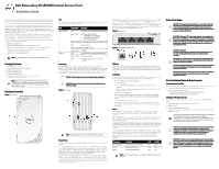
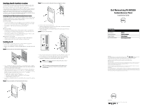
Identifying Specific Installation Locations The W-IAP205H access point must be installed onto a Dell approved wall or desk mount kit (sold separately). Additional The AP should be oriented vertically, with Ethernet ports facing downward to facilitate maximum antenna gain. Use the AP placement map generated by the Dell Visual RF Plan software application to determine the proper installation location(s). Each location should be as close as possible to the center of the intended coverage area and should be free from obstructions or obvious sources of interference. These RF absorbers/reflectors/ interference sources will impact RF propagation and should be accounted for during the planning phase and adjusted for in the Visual RF plan. Identifying Known RF Absorbers/Reflectors/Interference Sources Identifying known RF absorbers, reflectors, and interference sources while in the field during the installation phase is critical. Make sure that these sources are taken into consideration when you attach an AP to its fixed location. RF absorbers include: Cement/concrete-Old concrete has high levels of water dissipation, which dries out the concrete, allowing for potential RF propagation. New concrete has high levels of water concentration in the concrete, blocking RF signals. Natural Items-Fish tanks, water fountains, ponds, and trees Brick RF reflectors include: Metal Objects-Metal pans between floors, rebar, fire doors, air conditioning/ heating ducts, mesh windows, blinds, chain link fences (depending on aperture size), refrigerators, racks, shelves, and filing cabinets. Do not place an AP between two air conditioning/heating ducts. Make sure that APs are placed below ducts to avoid RF disturbances. RF interference sources include: Microwave ovens and other 2.4 or 5 GHz objects (such as cordless phones) Cordless headset such as those used in call centers or lunch rooms Installing the AP The W-IAP205H is designed to mount into a variety of electrical gang boxes. 1. Remove the existing data wall plate (if applicable). 2. Remove any existing RJ-45 connectors (typically snap-in) or cut/remove the UTP cable. Figure 5 Removing Wall Plate (US Single Gang Outlet Box Shown) Figure 7 Bracket to Gang Box (Worldwide Single Gang Outlet Box Shown) 6. Connect cables to the back of the AP. 7. Align the mounting slots on the back of the AP with the corresponding mounting posts on the wall mount as shown in Figure 8. 8. Push the AP against the posts and downward until the posts engage the slots at the top of the slots. Figure 8 Attaching AP to Wall Mount 3. Use a short Ethernet cable (sold separately) to connect the E0 port to an RJ-45 connector or crimp an RJ-45 plug (not supplied) on the cable and insert in the E0 port. Do the same for the PT port, if used. 4. Align the mounting holes of the W-IAP205H mounting bracket with mounting holes in the gang box, as shown in Figure 6 and Figure 7. For worldwide single gang outlet box, the mounting bracket has two sets of mounting holes to meet the individual installation position requirement. See Figure 7 for details. The applicable standards for the wall boxes are: IEC 60670-1, GB17466, BS4662 and DIN49073 for Worldwide ANSI/NEMA OS 1 and OS 2 for US 5. Insert the two included machine screws and tighten them to secure the mounting bracket. Figure 6 Bracket to Gang Box (US Single Gang Outlet Box Shown) 9. Once the AP is fastened onto the wall mount, insert the T8H Torx security screw into the hole located on the upper-right edge of the wall mount and tighten. 10. If not using PoE, connect the AC-to-DC power adapter (AP-AC-48V36 sold separately) to the DC power socket located on the side of the AP. NOTE: For additional specifications on this product, please refer to the data sheet at dell.com. NOTE: For regulatory and safety information on this product refer to the Regulatory Compliance and Safety Information guide included with this product. Dell Networking W-IAP205H Instant Access Point Installation Guide Contacting Dell Web Site Support Main Website Contact Information Support Website Documentation Website dell.com dell.com/contactdell dell.com/support dell.com/support/manuals Copyright © 2015 Aruba Networks, Inc. Aruba Networks trademarks include , Aruba Networks®, Aruba Wireless Networks®, the registered Aruba the Mobile Edge Company logo, and Aruba Mobility Management System®. Dell™, the DELL™ logo, and PowerConnect™ are trademarks of Dell Inc. All rights reserved. Specifications in this manual are subject to change without notice. Originated in the USA. All other trademarks are the property of their respective owners. Open Source Code Certain Aruba products include Open Source software code developed by third parties, including software code subject to the GNU General Public License (GPL), GNU Lesser General Public License (LGPL), or other Open Source Licenses. The Open Source code used can be found at this site: http://www.arubanetworks.com/open_source Includes software from Litech Systems Design. The IF-MAP client library copyright 2011 Infoblox, Inc. All rights reserved. This product includes software developed by Lars Fenneberg, et al. Legal Notice The use of Aruba Networks, Inc. switching platforms and software, by all individuals or corporations, to terminate other vendors' VPN client devices constitutes complete acceptance of liability by that individual or corporation for this action and indemnifies, in full, Aruba Networks, Inc. from any and all legal actions that might be taken against it with respect to infringement of copyright on behalf of those vendors. www.dell.com Dell Networking W-IAP205H Instant Access Point | Installation Guide Part Number 0511813-01 | May 2015
-
 1
1 -
 2
2
 |
 |
