Dell W-Series 304 W-Series 300 Access Points Online Installation Guide - Page 2
External Antenna Connectors, USB Port, Console Port, Ethernet Port, Kensington
 |
View all Dell W-Series 304 manuals
Add to My Manuals
Save this manual to your list of manuals |
Page 2 highlights
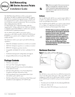
LED Color/ State Meaning System Status (Left) Radio Status (Right) Off Device powered off GreenBlinking* Device booting, not ready for use Green- Solid Device ready for use, no restrictions GreenFlashing** Device ready for use, uplink negotiated in sub optimal speed (
-
 1
1 -
 2
2 -
 3
3 -
 4
4 -
 5
5
 |
 |

Dell Networking 300 Series Access Points
|
Installation Guide
2
* Blinking: 1s on/1s off
**Flashing: off a fraction of a second every 2s
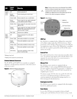
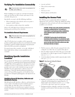
External Antenna Connectors
The W-AP304 and W-IAP304 access points are equipped
with three external antenna connectors on the front corners
of the access point.
Figure 2
External Antenna Connectors
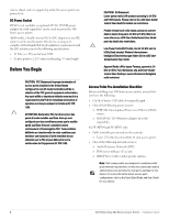
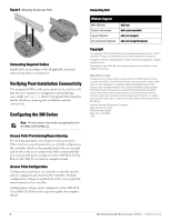
Figure 3
Back Panel
USB Port
The 300 Series is equipped with a USB port for connectivity
with cellular modems and other USB client devices. When
powered by an 802.3at PoE or DC power source, the USB port
can supply power up to 5W/1A. The USB interface is disabled
when the access point is powered by an 802.3af PoE source
(power-save mode).
Console Port
The serial console port is a 4-pin connector covered by a dust
cover. An optional serial adapter cable (AP-CBL-SER) is sold
separately to connect the device to a serial terminal or a
laptop for direct local management.
Ethernet Port
The 300 Series access points are equipped with one
10/100/1000Base-T auto-sensing MDI/MDX Ethernet port.
This port supports wired-network connectivity, in addition to
Power over Ethernet (PoE) from IEEE 802.3af and 802.3at
compliant power sources.
This device accepts 56V DC (802.3at), or 48V DC (802.3af)
nominal as a standard powered device (PD) from power
sourcing equipment, including PoE midspan injector or a
PoE-sourcing network infrastructure.
Kensington Lock Slot
The 300 Series access points are equipped with a Kensington
lock slot for additional security.
Reset Button
To reset the 300 Series access points to factory default
settings, press and hold down the reset button using a small,
LED
Color/
State
Meaning
System
Status
(Left)
Off
Device powered off
Green-
Blinking
*
Device booting, not ready for use
Green- Solid
Device ready for use, no restrictions
Green-
Flashing
**
Device ready for use, uplink negotiated
in sub optimal speed (<1Gbps)
Amber- Solid
Device ready for use; power-save mode
(802.3af PoE)
Amber-
Flashing
Device ready for use; power-save mode
(802.3af PoE), uplink negotiated in sub
optimal speed (<1Gbps)
Red- Solid
System error condition
Radio
Status
(Right)
Off
Device powered off, or both radios
disabled
Green- Solid
Both radios enabled in access mode
Green-
Blinking
One radio enabled in access mode
Amber- Solid
Both radios enabled in monitor mode
Amber-
Blinking
One radio enabled in monitor mode
Alternating
One radio enabled in access mode,
other in monitor mode
ANT0
ANT1
ANT2
Note:
The Equivalent Isotropically Radiated Power (EIRP)
levels for all external antenna devices must not exceed the
regulatory limit set by the host country/domain.
Installers are required to record the antenna gain for this
device in the system management software.
CONSOLE
12V
1A
ENET
600mA
57V
Console Port
Ethernet Port
USB Port
Reset
Button
DC Power Socket
Kensington
Lock