Dell W-Series 304 W-Series 300 Access Points Online Installation Guide - Page 4
Verifying Pre-Installation Connectivity, Identifying Specific Installation, Locations, Installing
 |
View all Dell W-Series 304 manuals
Add to My Manuals
Save this manual to your list of manuals |
Page 4 highlights
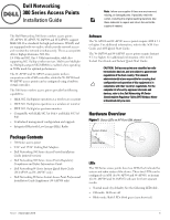
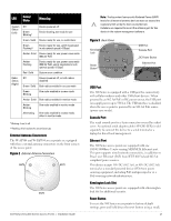
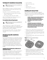
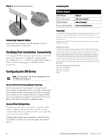
Verifying Pre-Installation Connectivity Note: The instructions in this section are applicable to the W-AP304 and W-AP305 only. Before installing access points in a network environment, make sure that they are able to locate and connect to the controller after power on. Specifically, you must verify the following conditions: When connected to the network, each access point is assigned a valid IP address Access points are able to locate the controller Refer to the AOS Quick Start Guide for instructions on locating and connecting to the controller. Pre-Installation Network Requirements Note: The instructions in this section are applicable to the W-AP304 and W-AP305 only. After WLAN planning is complete and the appropriate products and their placement have been determined, the Dell controller(s) must be installed and initial setup performed before the Dell access points are deployed. For initial setup of the controller, refer to the AOS Quick Start Guide for the software version installed on your controller. Identifying Specific Installation Locations You can mount the 300 Series access point on the ceiling or a wall. Use the access point placement map generated by Dell VisualRF Plan software application to determine the proper installation location(s). Each location should be as close as possible to the center of the intended coverage area and should be free from obstructions or obvious sources of interference. These RF absorbers/reflectors/interference sources will impact RF propagation and should have been accounted for during the planning phase and adjusted for in RF plan. Identifying Known RF Absorbers, Reflectors and Interference Sources Identifying known RF absorbers, reflectors, and interference sources while in the field during the installation phase is critical. Make sure that these sources are taken into consideration when you attach an access point to its fixed location. Examples of sources that degrade RF performance include: Dell Networking 300 Series Access Points | Installation Guide Cement and brick Objects that contain water Metal Microwave ovens Wireless phones and headsets Installing the Access Point The 300 Series access points ship with two ceiling rail adapters for 9/16" and 15/16" ceiling rails. Additional ceiling rail adapters for other rail styles and wall mount adapters are available as accessory kits. CAUTION: All Dell access points should be professionally installed by certified technician. The technician is responsible for ensuring that grounding is available that meets applicable regional regulatory and electrical standards. ATTENTION: Tous les points d'accès Dell doivent impérativement être installés par un professionnel agréé. Ce dernier doit s'assurer que l'appareil est mis à la terre et que le circuit de mise à la terre est conforme aux codes électriques nationaux en vigueur. 1. Pull the necessary cables through a prepared hole in the ceiling tile near where the access point will be placed. 2. Place the adapter against the back of the access point with the adapter at an angle of approximately 30 degrees to the tabs (see Figure 4). 3. Twist the adapter clockwise until it snaps into place in the tabs (see Figure 4). Figure 4 Attaching the Ceiling Rail Adapter 4. Hold the access point next to the ceiling tile rail with the ceiling tile rail mounting slots at approximately a 30degree angle to the ceiling tile rail (see Figure 5). Make sure that any cable slack is above the ceiling tile. 5. Pushing toward the ceiling tile, rotate the access point clockwise until the device clicks into place on the ceiling tile rail. 4
-
 1
1 -
 2
2 -
 3
3 -
 4
4 -
 5
5
 |
 |
