Dell W-Series 324 320 Series Access Points Installation Guide - Page 1
Dell W-Series 324 Manual
 |
View all Dell W-Series 324 manuals
Add to My Manuals
Save this manual to your list of manuals |
Page 1 highlights
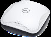
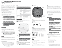
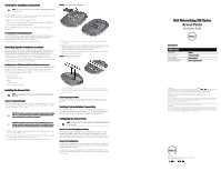
Dell Networking 320 Series Access Points Installation Guide The Dell 320 Series access points (W-AP324, W-AP325, W-IAP324, and W-IAP325) support IEEE 802.11ac standards for high-performance WLAN, and are equipped with two dual-band radios, which can provide access and monitor the network simultaneously. Multi-user Multiple-input, Multiple-output (MU-MIMO) technology allows these access points to deliver high-performance 802.11n 2.4 GHz and 802.11ac 5 GHz functionality, while also supporting 802.11a/b/g wireless services. The W-AP324 and W-AP325 access points work in conjunction with a Dell controller, while the W-IAP324 and W-IAP325 Instant access points can be configured using a built-in virtual controller. The 320 Series access points provide the following capabilities: Dual wireless transceiver IEEE 802.11a/b/g/n/ac operation as a wireless access point IEEE 802.11a/b/g/n/ac operation as a wireless air monitor and spectrum analyzer Compatibility with IEEE 802.3at PoE+ and 802.3af PoE Centralized management configuration and upgrades Integrated Bluetooth Low Energy (BLE) radio CAUTION: Access points are classified as radio transmission devices and are subject to government regulations of the deploying country. The network administrators are responsible for ensuring that the configuration and operation of this equipment is in compliance with their country's regulations. Specifically, access points must use channel assignments appropriate to the locale in which the access points will be used. For a complete list of approved channels in your country, refer to the Dell Networking W-Series Downloadable Regulatory Table (DRT) Release Notes at download.dell-pcw.com. ATTENTION: Les points d'accès sont considérés comme appareils de transmission radio et sont soumis aux réglementations gouvernementales du pays dans lequel ils sont déployés. Le ou les administrateurs réseau doivent s'assurer que la configuration et le fonctionnement de cet équipement sont conformes aux normes de leurs pays. De façon plus précise, les points d'accès doivent employer des canaux adaptés à leur emplacement physique. Pour obtenir une liste complète des canaux approuvés dans votre pays, reportez-vous aux notes de version Dell Networking W-Series Downloadable Regulatory Table (DRT) à l'adresse download.dell-pcw.com. Package Contents Dell 320 Series Access Point 9/16" and 15/16" Ceiling Rail Adapters Dell Networking 320 Series Access Points Installation Guide (this document) Dell Networking 320 Series Access Points Regulatory Compliance and Safety Information Guide Dell Networking W-Series Instant Access Point Professional Installation Guide Supplement (Instant access points only) Dell Networking W-Series Instant Quick Start Guide (Instant access points only) NOTE: Inform your supplier if there are any incorrect, missing, or damaged parts. If possible, retain the carton, including the original packing materials. Use these materials to repack and return the unit to the supplier if needed. Software The W-AP324 and W-AP325 access points require AOS 6.4.4 or higher. For additional information, refer to the Dell Networking W-Series ArubaOS User Guide and Dell Networking W-Series ArubaOS Quick Start Guide. The W-IAP324 and W-IAP325 Instant access points require Instant 4.2.1 or higher. For additional information, refer to the Dell Networking W-Series Instant User Guide and Dell Networking W-Series Instant Quick Start Guide. Hardware Overview Figure 1 LEDs System Status Radio Status LEDs The 320 Series access points have two LEDs that indicate the system and radio status of the device. LED System Status (Left) Radio Status (Right) Color/State Off Green/AmberAlternating Green- Solid Amber- Solid Green or AmberFlashing Red Off Green- Solid Amber- Solid Green/AmberAlternating Meaning Device powered off Device booting; not ready Device ready Device ready; power-save mode (802.3af PoE): Single radio USB disabled Restricted mode: Uplink negotiated in sub optimal speed; or Radio in non-high throughput mode System error condition Device powered off, or both radios disabled Both radios enabled in access mode Both radios enabled in monitor mode One radio enabled in access mode, one enabled in monitor mode External Antenna Connectors The 324 model access points are equipped with four external antenna connectors located on the front corners of the access point (see Figure 2). Figure 2 External Antenna Connectors ANT1 ANT0 ANT2 ANT3 CAUTION: Devices with external antennas must use manufacturer-approved antennas only. The administrators are responsible for ensuring that the Equivalent Isotropically Radiated Power (EIRP) levels for external antenna devices are compliant with the regulatory standards of the host country/domain. Installers are required to record the antenna gain (dBi) for this device in the system management software. ATTENTION: Les appareils munis d'antennes externes doivent utiliser uniquement des antennes certifiées par le fabricant. Le ou les administrateurs doivent s'assurer que les niveaux de puissance isotrope rayonnée équivalente (PIRE) de tous les appareils munis d'antennes externes sont conformes aux normes réglementaires du pays/domaine hôte. Le ou les installateurs doivent enregistrer le gain d'antenne (dBi) de cet appareil dans le logiciel de gestion du système. USB Interface The 320 Series access points are equipped with a USB port for connectivity with cellular modems and other USB client devices. When powered by an 802.3at PoE+ or DC source, the USB port can supply power up to 5W. NOTE: The USB port is disabled when the access point is powered by an 802.3af PoE source. Figure 3 Bottom Panel USB Port Ethernet Ports Console Port 12V . . . 2.5A DC Power Socket Reset Button Kensington Lock BLE Radio Console Port The serial console port allows the user to connect the access point to a serial terminal or a laptop for direct local management. This port is an RJ-45 connector with the pin-outs shown in Figure 4. Connect it directly to a terminal or terminal server using an Ethernet cable. Figure 4 Serial Port Pin-Out Ethernet Ports The 320 Series access points are equipped with two 10/100/1000 Base-T (RJ-45) autosensing, MDI/MDX wired-network connectivity ports, ENET0 and ENET1. These ports support IEEE 802.3af and 802.3at Power over Ethernet (PoE) compliant sources, accepting 56V DC (nominal) as a standard defined Powered Device (PD) from a Power Sourcing Equipment (PSE), such as a PoE midspan injector, or network infrastructure that supports PoE. The Ethernet ports are on the bottom of the access points. The ports have RJ-45 female connectors with the pin-outs shown in Figure 5. Figure 5 Gigabit Ethernet Port Pin-Out 1000Base-T Gigabit Ethernet Port RJ-45 Female Pin-Out 1 2 3 4 5 6 7 8 Signal Name BI_DA+ BI_DABI_DB+ BI_DC+ BI_DCBI_DBBI_DD+ BI_DD- Function Bi-directional pair +A Bi-directional pair -A Bi-directional pair +B Bi-directional pair +C Bi-directional pair -C Bi-directional pair -B Bi-directional pair +D Bi-directional pair -D Kensington Lock Slot The 320 Series access points are equipped with a Kensington lock slot for additional security. Reset Button The reset button can be used to return the access point to factory default settings. To reset the access point, refer to the steps below: 1. Power-off the access point. 2. Press and hold the reset button using a small, narrow object, such as a paperclip. 3. Power-on the access point without releasing the reset button. The power LED will flash within 5 seconds. 4. Release the reset button. The power LED will flash again within 15 seconds indicating that the reset is completed. The access point will now continue to boot with the factory default settings. Power The ENET0 and ENET1 ports support PoE-in, allowing either port to draw power from an 802.3at PoE+ source (recommended) or an 802.3af PoE source. When both PoE and DC power sources are available, the access point will default to using the DC power source. The 320 Series access points have a single 12V/30W DC power jack socket to support the AP-AC-12V30UN AC-to-DC adapter (sold separately). Power Modes The 320 Series access points can operate in two power modes. The modes are not configurable and determined by the access point based on the amount of power available. The 320 Series access points operate without restrictions when powered by a DC or 802.3at PoE+ source. When powered by an 802.3af PoE source, the following restrictions apply: Second Ethernet port disabled USB interface disabled 2.4 GHz in 1x1:1 mode Before You Begin CAUTION: FCC Statement: Improper termination of access points installed in the United States configured to non-US model controllers will be in violation of the FCC grant of equipment authorization. Any such willful or intentional violation may result in a requirement by the FCC for immediate termination of operation and may be subject to forfeiture (47 CFR 1.80). ATTENTION: Déclaration FCC l'arrêt incorrect des points d'accès installés aux États-Unis qui sont configurés sur des contrôleurs autres que le modèle agréé aux États-Unis est considéré comme contrevenant à l'homologation FCC. Toute violation délibérée ou intentionnelle de cette condition peut entraîner une injonction d'arrêt immédiat de son utilisation par la FCC et peut déboucher sur la confiscation de l'équipement (47 CFR 1.80). CAUTION: EU Statement: Lower power radio LAN product operating in 2.4 GHz and 5 GHz bands. Please refer to the User Guide for details on restrictions. Produit réseau local radio basse puissance operant dans la bande fréquence 2.4 GHz et 5 GHz. Merci de vous referrer au manuel utilisateur pour les details des restrictions. Low Power FunkLAN Produkt, das im 2.4 GHz und im 5 GHz Band arbeitet. Weitere Informationen bezlüglich Einschränkungen finden Sie im benutzerhandbuch. Apparati Radio LAN a bassa Potenza, operanti a 2.4 GHz e 5 GHz. Fare riferimento alla manuale utente per avere informazioni detagliate sulle restrizioni. Access Point Pre-Installation Checklist Before installing your 320 Series access point, ensure that you have the following: CAT5E or CAT6 UTP cable of required length One of the following power sources: IEEE 802.3at or 802.3af-compliant Power over Ethernet (PoE) source. The PoE source can be any power source equipment (PSE) controller or midspan PSE device Dell AP-AC-12V30UN AC-to-DC adapter kit (sold separately) For W-AP324 and W-AP325 access points only: Dell Controller provisioned on the network Layer 2/3 network connectivity to the access point One of the following network services: Aruba Discovery Protocol (ADP) DNS server with an "A" record DHCP Server with vendor-specific options NOTE: Dell access points are designed in compliance with governmental requirements, so that only authorized network administrators are permitted to change the settings for this device. For more information about access point configuration, refer to the Quick Start Guide and User Guide for your device.
-
 1
1 -
 2
2
 |
 |