Dell W-Series 324 320 Series Access Points Installation Guide - Page 2
Dell Networking 320 Series
 |
View all Dell W-Series 324 manuals
Add to My Manuals
Save this manual to your list of manuals |
Page 2 highlights
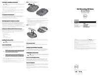
Verifying Pre-Installation Connectivity NOTE: The instructions in this section are applicable to the W-AP324 and W-AP325 access points only. Before installing access points in a network environment, make sure that they are able to locate and connect to the controller after power on. Specifically, you must verify the following conditions: When connected to the network, each access point is assigned a valid IP address Access points are able to locate the controller Refer to the Quick Start Guide for instructions on locating and connecting to the controller. Pre-Installation Network Requirements After WLAN planning is complete and the appropriate products and their placement have been determined, the Dell controller(s) must be installed and initial setup completed before the Dell access points are deployed. For initial setup of the controller, refer to Quick Start Guide. Identifying Specific Installation Locations You can mount the 320 Series access point on a wall or on the ceiling. Use the access point placement map generated by the Dell VisualRF Plan software application to determine the proper installation location(s). Each location should be as close as possible to the center of the intended coverage area and should be free from obstructions or obvious sources of interference. These RF absorbers/reflectors/ interference sources will impact RF propagation and should be accounted for during the planning phase and adjusted for in the RF plan. Identifying Known RF Absorbers/Reflectors/Interference Sources Identifying known RF absorbers, reflectors, and interference sources while in the field during the installation phase is critical. Make sure that these sources are taken into consideration when you attach an access point to its fixed location. Examples of sources that degrade RF performance include: Cement and brick Objects that contain water Metal Microwave ovens Wireless phones and headsets Installing the Access Point NOTE: Service to all Dell Networking products should be performed by a qualified technician. Using the Ceiling Rail Adapter The 320 Series access points are shipped with two ceiling rail adapters for 9/16" and 15/16" ceiling rails. Additional wall mount adapters and ceiling rail adapters for other rail styles are available as accessory kits . CAUTION: The installer is responsible for securing the access point onto the ceiling tile rail in accordance with the steps below. Failure to properly install this product may result in physical injury and/or damage to property. ATTENTION: L'installateur est chargé de sécuriser le point d'accès sur le rail de montage au plafond en suivant la procédure ci-après. Toute installation incorrecte du produit peut entraîner des blessures physiques et/ou des dommages matériels. 1. Pull the necessary cables through a prepared hole in the ceiling tile close to where the access point will be placed. 2. Place the adapter against the back of the access point with the adapter at an angle of approximately 30 degrees to the tabs (see Figure 6). 3. Twist the adapter clockwise until it snaps in place into the tabs (see Figure 6). Figure 6 Attaching the Ceiling Rail Adapter 4. If necessary, connect the console cable to the console port on the back of the access point. 5. Hold the access point next to the ceiling tile rail with the ceiling tile rail mounting slots at approximately a 30-degree angle to the ceiling tile rail (see Figure 7). Make sure that any cable slack is above the ceiling tile. 6. Pushing toward the ceiling tile, rotate the access point clockwise until the device clicks in place on the ceiling tile rail. Figure 7 Mounting the Access Point 7. On the 324 model access points, install the external antennas according to the manufacturer's instructions, and connect the antennas to the antenna interfaces on the access point. Connecting Required Cables Install cables in accordance with all applicable local and national regulations and practices. Verifying Post-Installation Connectivity The integrated LEDs on the access point can be used to verify that the device is receiving power and initializing successfully (see Table 1). Refer to the Quick Start Guide for further details on verifying post-installation network connectivity. Configuring the Access Point NOTE: The instructions for this section are applicable to the W-AP324 and W-AP325 access points only. Access Point Provisioning/Reprovisioning Provisioning parameters are unique to each access point. These local access point parameters are initially configured on the controller, and then pushed out to the access points and stored on the access points. Dell recommends that provisioning settings be configured via the AOS Web UI only. Refer to the User Guide for details. Access Point Configuration Configuration parameters are network or controller specific. They are configured and stored on the controller and then pushed out to the access points. These parameters remain stored on the controller. Configuration settings can be configured via the AOS Web UI or CLI. Refer to the User Guide or Dell Networking W-Series ArubaOS Command-Line Interface Reference Guide for details. Dell Networking 320 Series Access Points Installation Guide Contacting Dell Website Support Main Website Contact Information Support Website Documentation Website dell.com dell.com/contactdell dell.com /support dell.com /support/manuals Copyright © 2015 Aruba Networks, Inc. Aruba Networks trademarks include , Aruba Networks®, Aruba Wireless Networks®, the registered Aruba the Mobile Edge Company logo, and Aruba Mobility Management System®. Dell™, the DELL™ logo, and PowerConnect™ are trademarks of Dell Inc. All rights reserved. Specifications in this manual are subject to change without notice. Originated in the USA. All other trademarks are the property of their respective owners. Open Source Code Certain Aruba products include Open Source software code developed by third parties, including software code subject to the GNU General Public License (GPL), GNU Lesser General Public License (LGPL), or other Open Source Licenses. The Open Source code used can be found at this site: http://www.arubanetworks.com/open_source Includes software from Litech Systems Design. The IF-MAP client library copyright 2011 Infoblox, Inc. All rights reserved. This product includes software developed by Lars Fenneberg, et al. Legal Notice The use of Aruba Networks, Inc. switching platforms and software, by all individuals or corporations, to terminate other vendors' VPN client devices constitutes complete acceptance of liability by that individual or corporation for this action and indemnifies, in full, Aruba Networks, Inc. from any and all legal actions that might be taken against it with respect to infringement of copyright on behalf of those vendors. dell.com Dell Networking 320 Series Access Points | Installation Guide Part Number 0511834-02| July 2015
-
 1
1 -
 2
2
 |
 |
