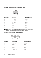
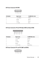
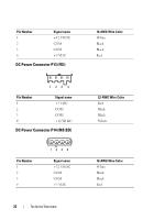
Dell XPS 630i Service Manual - Page 21
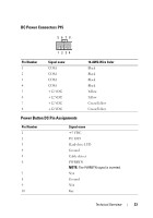
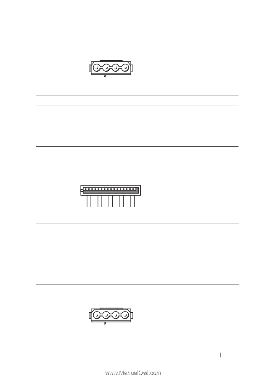
DC Power Connector P8 (PHY), DC Power Connectors P9 and P10 (Bay1 SATA and Bay2 SATA), 12 VB DC, White
 |
View all Dell XPS 630i manuals
Add to My Manuals
Save this manual to your list of manuals |
Page 21 highlights
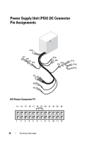
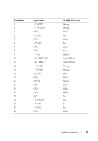
DC Power Connector P8 (PHY) Pin Number 1 2 3 4 1234 Signal name +12 VB DC COM COM +5 VDC 18-AWG Wire Color White Black Black Red DC Power Connectors P9 and P10 (Bay1 SATA and Bay2 SATA) 5 432 1 Pin Number 1 2 3 4 5 Signal name +3.3 VDC COM +5 VDC COM +12 VC DC 18-AWG Wire Color Orange Black Red Black Blue/White DC Power Connector P11 and P12 (BAY and BAY2) 1234 Technical Overview 21
-
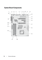
 1
1 -
2
-
3
-
4
-
5
-
6
-
7
-
8
-
9
-
10
-
11
-
12
-
13
-
14
-
15
-
 16
16 -
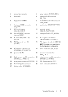 17
17 -
 18
18 -
 19
19 -
 20
20 -
 21
21 -
 22
22 -
 23
23 -
 24
24 -
 25
25 -
 26
26 -
27
-
28
-
29
-
30
-
31
-
32
-
33
-
34
-
35
-
36
-
37
-
38
-
39
-
40
-
41
-
42
-
43
-
44
-
45
-
46
-
47
-
48
-
49
-
50
-
51
-
52
-
53
-
54
-
55
-
56
-
57
-
58
-
59
-
60
-
61
-
62
-
63
-
64
-
65
-
66
-
67
-
68
-
69
-
70
-
71
-
72
-
73
-
74
-
75
-
76
-
77
-
78
-
79
-
80
-
81
-
82
-
83
-
84
-
85
-
86
-
87
-
88
-
89
-
90
-
91
-
92
-
93
-
94
-
95
-
96
-
97
-
98
-
99
-
100
-
101
-
102
-
103
-
104
-
105
-
106
-
107
-
108
-
109
-
110
-
111
-
112
-
113
-
114
-
115
-
116
-
117
-
118
-
119
-
120
 |
 |
Technical Overview
21
DC Power Connector P8 (PHY)
DC Power Connectors P9 and P10 (Bay1 SATA and Bay2 SATA)
DC Power Connector P11 and P12 (BAY and BAY2)
Pin Number
Signal name
18-AWG Wire Color
1
+12 VB DC
White
2
COM
Black
3
COM
Black
4
+5 VDC
Red
Pin Number
Signal name
18-AWG Wire Color
1
+3.3 VDC
Orange
2
COM
Black
3
+5 VDC
Red
4
COM
Black
5
+12 VC DC
Blue/White
1
2
3
4
5
4
3
2
1
1
2
3
4