Denon AVR-1705 Owners Manual - Page 10
Connections - remote
 |
View all Denon AVR-1705 manuals
Add to My Manuals
Save this manual to your list of manuals |
Page 10 highlights
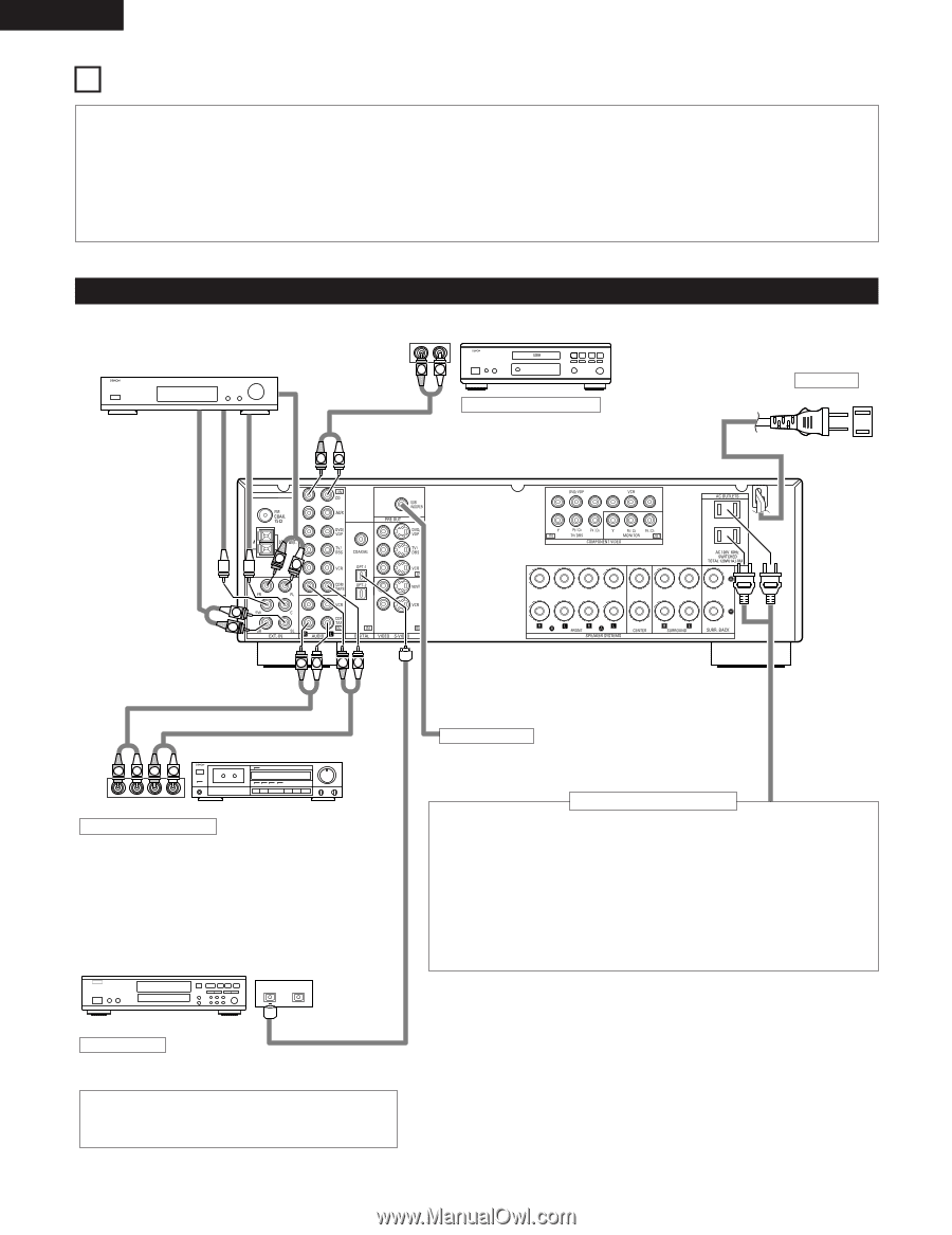
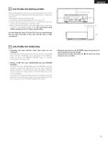
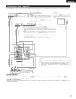
ENGLISH 8 CONNECTIONS • Do not plug in the power cord until all connections have been completed. • Be sure to connect the left and right channels properly (left with left, right with right). • Insert the plugs securely. Incomplete connections will result in the generation of noise. • Use the AC OUTLETS for audio equipment only. Do not use them for hair driers, etc. • Note that binding pin plug cords together with power cords or placing them near a power transformer will result in generating hum or other noise. • Noise or humming may be generated if a connected audio equipment is used independently without turning the power of this unit on. If this happens, turn on the power of the this unit. Connecting the audio components Decoders with 6-channel analog outputs, etc. LINE OUT LINE OUT RL OUTPUT RL CD player RL DIGITAL AUDIO Connecting a CD player Connect the CD player's analog output jacks (ANALOG OUTPUT) to this unit's CD jacks using pin plug cords. AC CORD AC 120V, 60Hz SURROUND SUB WOOFER CENTER FRONT R L L R RL RL LINE IN LINE OUT R LR L Tape deck or CD recorder R LRL INPUT OUTPUT Connecting a tape deck Connections for recording: Connect the tape deck's recording input jacks (LINE IN or REC) to this unit's tape recording (OUT) jacks using pin plug cords. Connections for playback: Connect the tape deck's playback output jacks (LINE OUT or PB) to this unit's tape playback (IN) jacks using pin plug cords. CD recorder, MD recorder or other component equipped with digital output jacks. OPTICAL B OUTPUT INPUT Subwoofer jack Connect the internal amplifier's subwoofer to the subwoofer terminal. (Refer to page 15.) Connecting the AC OUTLETS AC OUTLETS • SWITCHED (total capacity - 120 W (1 A.)) The power to these outlets is turned on and off in conjunction with the POWER switch on the main unit, and when the power is switched between on and standby from the remote control unit. No power is supplied from these outlets when this unit's power is at standby. Never connect equipment whose total capacity is above 120 W (1 A.) NOTE: Only use the AC OUTLETS for audio equipment. Never use them for hair driers, TVs or other electrical appliances. DIGITAL jacks Use these for connections to audio equipment with digital output. Refer to page 26 for instructions on setting this terminal. • Use 75 Ω/ohms cable pin cords (sold separately) for coaxial connections. • Use optical cables (sold separately) for optical connections. 10
-
 1
1 -
2
-
3
-
4
-
 5
5 -
 6
6 -
 7
7 -
 8
8 -
 9
9 -
 10
10 -
 11
11 -
 12
12 -
 13
13 -
 14
14 -
 15
15 -
16
-
17
-
18
-
19
-
20
-
21
-
22
-
23
-
24
-
25
-
26
-
27
-
28
-
29
-
30
-
31
-
32
-
33
-
34
-
35
-
36
-
37
-
38
-
39
-
40
-
41
-
42
-
43
-
44
-
45
-
46
-
47
-
48
-
49
-
50
-
51
-
52
-
53
-
54
-
55
-
56
-
57
-
58
-
59
-
60
-
61
-
62
-
63
-
64
-
65
-
66
-
67
-
68
-
69
-
70
-
71
-
72
-
73
-
74
-
75
 |
 |