Denon AVR-1905 Owners Manual - Page 20
Speaker system layout, NOTES - receiver
 |
View all Denon AVR-1905 manuals
Add to My Manuals
Save this manual to your list of manuals |
Page 20 highlights
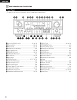
ENGLISH Auto Tuner Presets System setup FM stations are received automatically and stored in the memory. A1 ~ A8 B1 ~ B8 C1 ~ C8 D1 ~ D8 E1 ~ E8 F1 ~ F8 G1 ~ G8 Default settings 87.5 / 89.1 / 98.1 / 107.9 / 90.1 / 90.1 / 90.1 / 90.1 MHz 520 / 600 / 1000 / 1400 / 1500 / 1710 kHz, 90.1 / 90.1 MHz 90.1 MHz 90.1 MHz 90.1 MHz 90.1 MHz 90.1 MHz NOTES: • The on-screen display signals are output with priority to the S-VIDEO MONITOR OUT jack during playback of a video component. For example, if the TV monitor is connected to both the AVR-1905/785's S-Video and video monitor output jacks and signals are input to the AVR1905/785 from a video source (VDP, etc.) connected to both the S-Video and video input jacks, the on-screen display signals are output with priority to the S-Video monitor output. If you wish to output the signals to the video monitor output jack, do not connect a cord to the SVIDEO MONITOR OUT jack. (For details, see page 30.) • The AVR-1905/785's on-screen display function is designed for use with high resolution monitor TVs, so it may be difficult to read small characters on TVs with small screens or low resolutions. • The setup menu is not displayed when headphone are being used. 2 Speaker system layout Basic system layout • The following is an example of the basic layout for a system consisting of 8 speaker systems and a television monitor: Subwoofer Center speaker system Surround back speaker system Front speaker systems Set these at the sides of the TV or screen with their front surfaces as flush with the front of the screen as possible. Surround speaker systems 20
-
 1
1 -
2
-
3
-
4
-
5
-
6
-
7
-
8
-
9
-
10
-
11
-
12
-
13
-
14
-
 15
15 -
 16
16 -
 17
17 -
 18
18 -
 19
19 -
 20
20 -
 21
21 -
 22
22 -
 23
23 -
 24
24 -
 25
25 -
26
-
27
-
28
-
29
-
30
-
31
-
32
-
33
-
34
-
35
-
36
-
37
-
38
-
39
-
40
-
41
-
42
-
43
-
44
-
45
-
46
-
47
-
48
-
49
-
50
-
51
-
52
-
53
-
54
-
55
-
56
-
57
-
58
-
59
-
60
-
61
-
62
-
63
-
64
-
65
-
66
-
67
-
68
-
69
-
70
-
71
-
72
-
73
-
74
-
75
-
76
-
77
 |
 |
