Dewalt D25052K Instruction Manual - Page 8
Trigger Switch Fig. 1, Reversing Lever Fig. 3, ASSEMBLY AND ADJUSTMENTS, Side Handle Fig. 2 - hammer drill
 |
View all Dewalt D25052K manuals
Add to My Manuals
Save this manual to your list of manuals |
Page 8 highlights
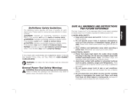
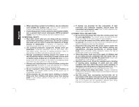
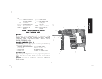
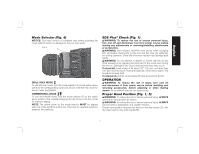
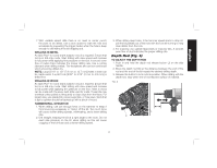
English This subcompact rotary hammer is a professional power tool. DO NOT let children come into contact with the tool. Supervision is required when inexperienced operators use this tool. ASSEMBLY AND ADJUSTMENTS WARNING: To reduce the risk of injury, turn unit off and disconnect it from power source before installing and removing accessories, before adjusting or when making repairs. An accidental start-up can cause injury. Side Handle (Fig. 2) WARNING: To reduce the risk of personal FIG. 2 injury, ALWAYS operate the tool with the side handle properly installed and securely tightened. Failure to do so may result in the side handle slipping during tool operation and subsequent loss of control. Hold tool with both hands to maximize control. A side handle comes assembled with this I rotary hammer. The side handle (C) can be fitted to suit both right-hand and left-hand users. TO ADJUST THE SIDE HANDLE 1. Loosen the side handle (C) by turning it C counterclockwise. 2. Rotate the side handle to the desired position. 3. Tighten the side handle by turning it clockwise until you are sure the side handle won't slip. TO CHANGE SIDES For right-hand users: slide the side handle clamp over the chuck, handle at the left. For left-hand users: slide the side handle clamp over the chuck, handle at the right. Trigger Switch (Fig. 1) To start the rotary hammer, depress the trigger switch (A). To stop rotary hammer, release the switch. NOTE: Use lower speeds for starting holes without a centerpunch, drilling in metal, plastics or ceramics, or driving screws. Higher speeds are better for drilling in masonry for maximum efficiency. VARIABLE SPEED The variable speed trigger switch (A) permits speed control. The farther the trigger switch is depressed, the higher the speed of the drill. Reversing Lever (Fig. 3) The reversing lever (G) is used to reverse the rotary hammer for backing out fasteners or jammed bits in drill-only mode. WARNING: When reversing to clear jammed bits, be ready for strong reactive FIG. 3 G torque. To reverse the rotary hammer, turn it off and align the reversing lever (G) with the yellow arrow pointing backward (viewed when holding drill in operating position). To position the lever for forward operation, turn the rotary hammer off and align the reversing lever (G) with the yellow arrow pointing forward (viewed when holding drill in operating position). 6
-
 1
1 -
2
-
 3
3 -
 4
4 -
 5
5 -
 6
6 -
 7
7 -
 8
8 -
 9
9 -
 10
10 -
 11
11 -
 12
12 -
 13
13 -
14
-
15
-
16
-
17
-
18
-
19
-
20
-
21
-
22
-
23
-
24
-
25
-
26
-
27
-
28
-
29
-
30
-
31
-
32
-
33
-
34
-
35
-
36
-
37
-
38
-
39
-
40
-
41
-
42
 |
 |