Dewalt D28066N Instruction Manual - Page 10
Save These Instructions For, Future Use, Components Fig. 1
 |
View all Dewalt D28066N manuals
Add to My Manuals
Save this manual to your list of manuals |
Page 10 highlights
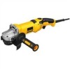
English Minimum Gauge for Cord Sets Volts Total Length of Cord in Feet (meters) Ampere Rating 120 V 25 (7.6) 50 (15.2) 100 (30.5) 150 (45.7) 240 V 50 100 200 300 (15.2) (30.5) (61.0) (91.4) More Not Than More Than AWG 0 6 18 16 16 14 6 10 18 16 14 12 10 12 16 16 14 12 12 16 14 12 Not Recommended SAVE THESE INSTRUCTIONS FOR FUTURE USE COMPONENTS (Fig. 1) WARNING: Never modify the power tool or any part of it. Damage or personal injury could result. A. Trigger Switch G2. 3" (76 mm) diameter B. Lock On Button (D28065, D28115, D28116) C. Spindle Lock Button D. Type 27 Guard E. Dust Ejection System™ (DES) F. Yellow Rubber Ring G1. 1-11/16" (43 mm) diameter stamped steel backing flange (D28065, D28066N, D28065N, D28116) H. Threaded locking flange I. Anti-Vibration Side Handle (not shown) J. Lock Off Button (D28066N, only) quick-change backing flange FIG. 1 C F 8 J B D A E E H G1 G2
-
 1
1 -
2
-
3
-
4
-
 5
5 -
 6
6 -
 7
7 -
 8
8 -
 9
9 -
 10
10 -
 11
11 -
 12
12 -
 13
13 -
 14
14 -
 15
15 -
16
-
17
-
18
-
19
-
20
-
21
-
22
-
23
-
24
-
25
-
26
-
27
-
28
-
29
-
30
-
31
-
32
-
33
-
34
-
35
-
36
-
37
-
38
-
39
-
40
-
41
-
42
-
43
-
44
-
45
-
46
-
47
-
48
-
49
-
50
-
51
-
52
-
53
-
54
-
55
-
56
-
57
-
58
-
59
-
60
-
61
-
62
-
63
-
64
-
65
-
66
-
67
-
68
-
69
-
70
-
71
-
72
-
73
-
74
-
75
-
76
 |
 |
