Dewalt D28066N Instruction Manual - Page 13
Mounting Guard, ASSEMBLY AND ADJUSTMENTS
 |
View all Dewalt D28066N manuals
Add to My Manuals
Save this manual to your list of manuals |
Page 13 highlights
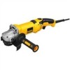
English 4-1/2" (115 mm) Sanding Flap Discs Type 27 guard Type 27 guard hubbed sanding flap disc 1-11/16" (43 mm) diameter quick-change backing flange non-hubbed sanding flap disc threaded locking flange ASSEMBLY AND ADJUSTMENTS WARNING: To reduce the risk of injury, turn unit off and disconnect it from power source before installing and removing accessories, before adjusting or when making repairs. Before reconnecting the tool, depress and release the trigger switch to ensure that the tool is off. An accidental startup can cause injury. Mounting Guard MOUNTING AND REMOVING GUARD (FIG. 2, 3) CAUTION: Guards must be used with all grinding wheels, cutting wheels, sanding flap discs, wire brushes, and wire wheels. The tool may be used without a guard only when sanding with conventional sanding discs. A Type 1 guard (intended for use with Type 1 cutting wheels and Type 27 wheels marked for cutting only) is available at extra cost from your local dealer or authorized service center. Grinding with wheels other than Type 27 and Type 29 require different accessory guards not included with the tool. A Type 27 guard is provided for use with a 1/4" (6.35 mm) thick, Type 27 wheel. 1. Open the guard latch (M). Align the lugs (K) on the guard with the slots (L) on the gear case. 2. Push the guard down until the guard lugs engage and rotate freely in the groove on FIG. 2 K the gear case hub. 3. With the guard latch open, rotate the guard (D) into the desired working position. The guard body should be positioned between the spindle and the operator to provide L maximum operator protection. M 4. Close the guard latch to secure the guard on the gear case. You should not be able to rotate the guard by hand when the latch is closed. Do not operate the grinder with a loose guard or the guard latch in open position. D 5. To remove the guard, open the guard latch, rotate the guard so that the arrows are aligned and pull up on the guard. 11
-
 1
1 -
2
-
3
-
4
-
5
-
6
-
7
-
 8
8 -
 9
9 -
 10
10 -
 11
11 -
 12
12 -
 13
13 -
 14
14 -
 15
15 -
 16
16 -
 17
17 -
 18
18 -
19
-
20
-
21
-
22
-
23
-
24
-
25
-
26
-
27
-
28
-
29
-
30
-
31
-
32
-
33
-
34
-
35
-
36
-
37
-
38
-
39
-
40
-
41
-
42
-
43
-
44
-
45
-
46
-
47
-
48
-
49
-
50
-
51
-
52
-
53
-
54
-
55
-
56
-
57
-
58
-
59
-
60
-
61
-
62
-
63
-
64
-
65
-
66
-
67
-
68
-
69
-
70
-
71
-
72
-
73
-
74
-
75
-
76
 |
 |
