Dewalt D28402N Instruction Manual - Page 6
ASSEMBLY AND ADJUSTMENTS, Rotating the Gear Case, Accessories - d28402 switch
 |
View all Dewalt D28402N manuals
Add to My Manuals
Save this manual to your list of manuals |
Page 6 highlights
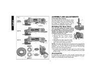
English FIG. 1 C D28402 D28402N F D28110 D28112 S IA B J K (D28402) L L K G H K ASSEMBLY AND ADJUSTMENTS ATTACHING SIDE HANDLE The side handle (E) can be fitted to either E side of the gear case in the threaded holes, as shown. Before using the tool, check that the handle is tightened securely. Use a wrench to firmly tighten the side handle. Rotating the Gear Case Turn off and unplug tool before making any adjustments or removing or installing accessories. Before reconnecting the tool, depress and release the trigger switch to ensure that the tool is off. 1. Remove guard and flanges from tool. 2. Remove the four corner screws attaching the gear case to motor housing. 90˚ 90˚ 3. Separating the gear case from motor housing not more than 1/4", rotate the gear case head to desired position. NOTE: If the gear case and motor housing become separated by more than 1/4", the tool must be serviced and re-assembled by a DEWALT service center. Failure to have the tool serviced may cause brush, motor and bearing failure. 3. Re-install screws to attach the gear case to the motor housing. Tighten screws to 18 in./lbs. torque. Overtightening could cause screws to strip. Accessories It is important to choose the correct guards, backing pads and flanges to use with grinder accessories. See pages 6-7 for information on choosing the correct accessories. 5
-
 1
1 -
 2
2 -
 3
3 -
 4
4 -
 5
5 -
 6
6 -
 7
7 -
 8
8 -
 9
9 -
 10
10 -
 11
11 -
 12
12 -
13
-
14
-
15
-
16
-
17
-
18
-
19
-
20
-
21
-
22
-
23
-
24
-
25
-
26
-
27
-
28
-
29
-
30
-
31
-
32
-
33
-
34
-
35
-
36
-
37
-
38
-
39
-
40
-
41
-
42
-
43
-
44
-
45
-
46
-
47
-
48
-
49
-
50
-
51
-
52
 |
 |
