Dewalt D28402N Instruction Manual - Page 8
/2 Sanding Flap Discs, Sanding Discs - grinder
 |
View all Dewalt D28402N manuals
Add to My Manuals
Save this manual to your list of manuals |
Page 8 highlights
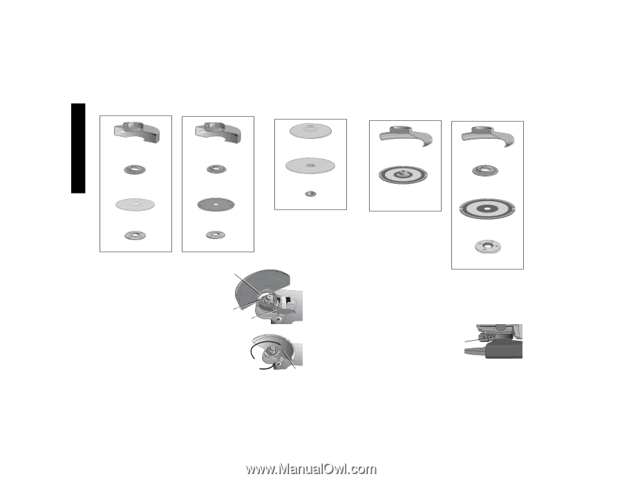
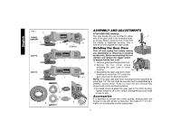
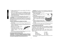
4-1/2" Cutting Wheels Sanding Discs 4-1/2" Sanding Flap Discs English Type 1 guard backing flange Type 1 guard backing flange abrasive cutting wheel diamond cutting wheel clamp nut clamp nut 1. Open the guard latch (M). Align N the lugs (N) on the guard with the slots (O) on the gear case. 2. Push the guard down until the guard lugs engage and rotate freely in the groove on the gear O case hub. M 3. With the guard latch open, rotate the guard (I) into the desired working po sition. The guard body should be posi- tioned between the spindle and the operator to provide maximum operator protection. rubber backing pad sanding disc threaded clamp nut Type 27 guard hubbed sanding flap disc Type 27 guard backing flange non-hubbed sanding flap disc threaded clamp nut 4. Close the guard latch to secure the guard on the gear case. You should not be able to rotate the guard by hand when the latch is closed. Do not operate the grinder with a loose guard or the clamp lever in open position. 5. To remove the guard, open the guard latch, rotate the guard so that the arrows are aligned and pull up on the guard. NOTE: The guard is pre-adjusted to the diameter of the gear case hub at the factory. If, after a period of time, the guard becomes P loose, tighten the adjusting screw (P) with clamp lever in the closed position. I 7
-
 1
1 -
2
-
 3
3 -
 4
4 -
 5
5 -
 6
6 -
 7
7 -
 8
8 -
 9
9 -
 10
10 -
 11
11 -
 12
12 -
 13
13 -
14
-
15
-
16
-
17
-
18
-
19
-
20
-
21
-
22
-
23
-
24
-
25
-
26
-
27
-
28
-
29
-
30
-
31
-
32
-
33
-
34
-
35
-
36
-
37
-
38
-
39
-
40
-
41
-
42
-
43
-
44
-
45
-
46
-
47
-
48
-
49
-
50
-
51
-
52
 |
 |